Paramount GEM User Guide
64 | P a g e
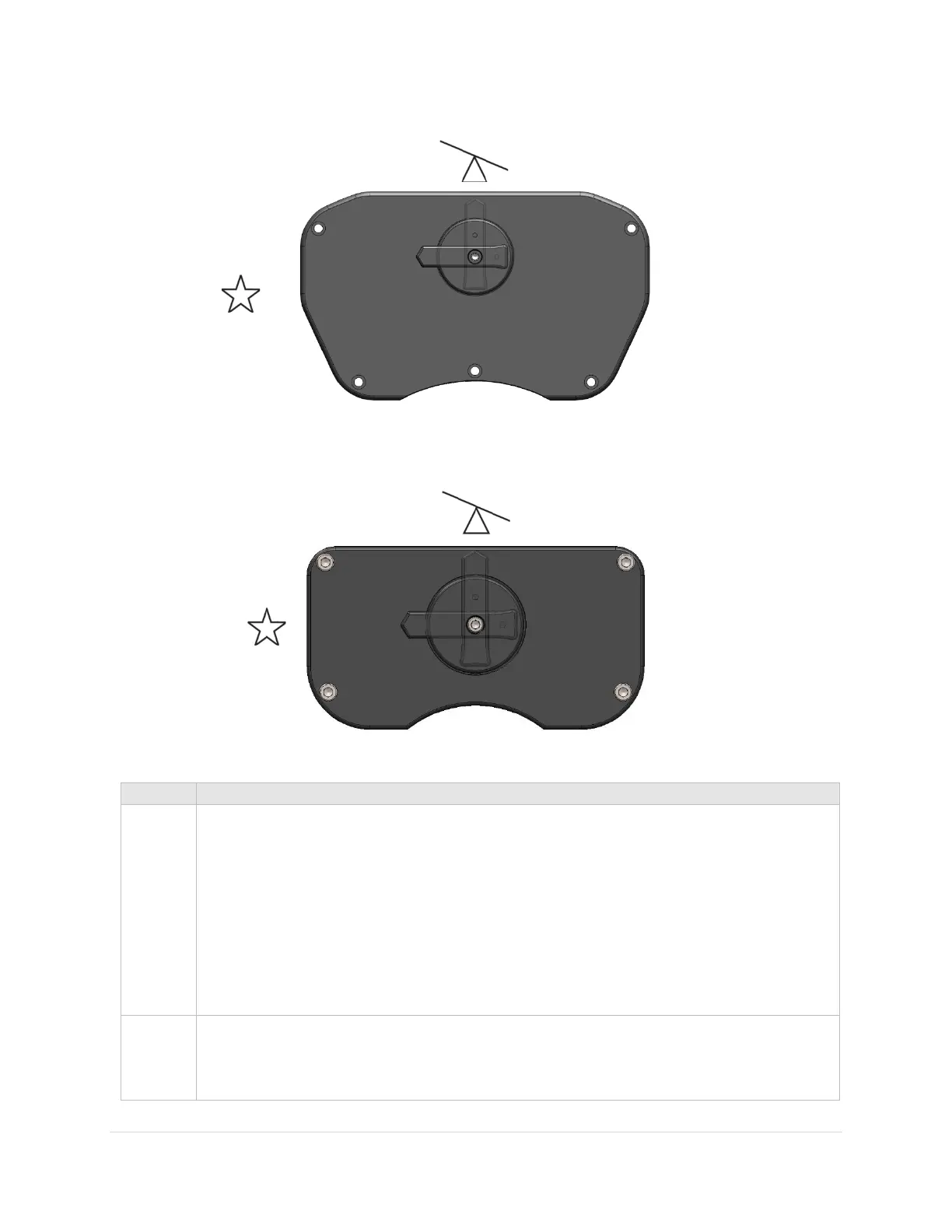
Figure 27: The Paramount ME two position switch.
Figure 28: The Paramount MYT and MX two position switch.
When the two-position switch (Figure 28) is in the balance position, the worm and gear
are separated, so the axis can rotate freely. When the switch is rotated to point at the
star (Track position), and the transport lock knob is in the unlock position, the mount is
ready for normal operation.
Notes:
• The transport lock knob is slightly recessed in the lock position.
• The transport lock knob should always be rotated clockwise when locking or
unlocking the axis.
When the two-position switch (Figure 27) is in the balance position, the worm and gear
are separated so the axis can rotate freely. When the switch is rotated to point at the
star, the mount is ready for normal operation.