Installing the Inverter
SolarEdge Installation Guide – MAN-01-00002-1.6
38
• Strip 8 mm (0.32'') for contact.
• Individual cable length 50 mm (2'').
Make sure to connect the PE (ground) connector first.
Veillez à relier le conducteur de PE (la terre) d'abord.
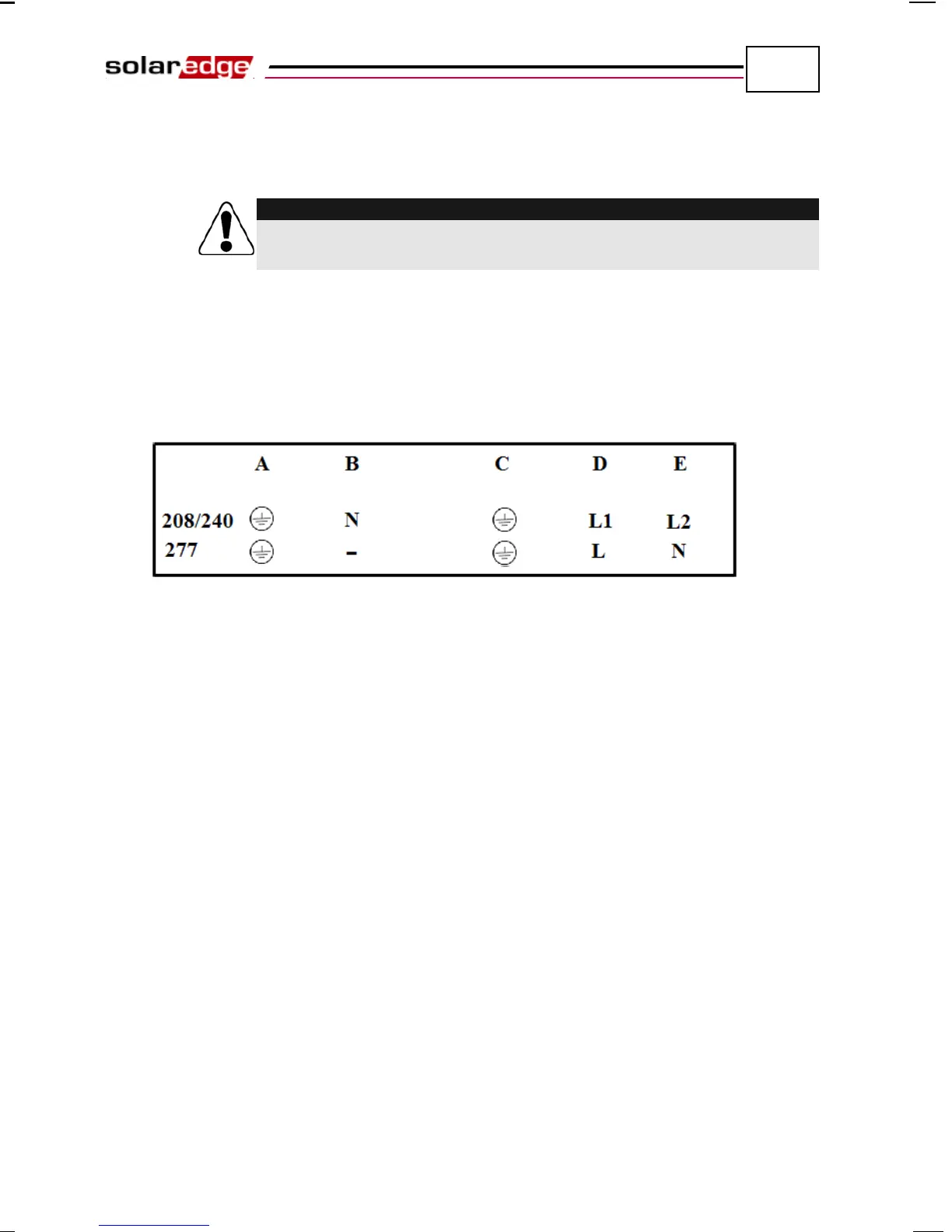
7 Insert the cable through the AC cable gland on the right and connect the
wires to the appropriate terminal connectors. Terminal blocks are labeled A
through E, as shown in Figure 15. Below the terminal blocks on the inverter
chassis, there is a label, shown in Figure 14, which illustrates how to connect
the wires when connecting to a 208V/240V grid or 277V grid. Be sure to
follow these connection instructions to ensure proper connection.
Figure 14: Terminal Wires Connection