Setting Up Communication
SolarEdge Installation Guide – MAN-01-00002-1.6
78
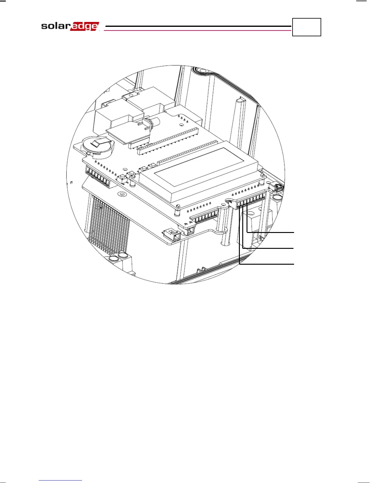
• Loosen the screws of each of the connectors B, A and G on RS-485-1.
Figure 45: RS485/RS232 Block Terminal
• The RS485 bus uses a four-wire telephone cable. Insert the cable via one
of the small cable glands.
• Connect wires into the B, A and G terminals on RS-485-1.
• All B wires on all inverters should be connected.
• All A wires on all inverters should be connected.
• All G wires on all inverters should be connected.
• Do not cross-connect B, A and G wires Do not insert wires into the
connectors labeled RS485-2.
A
B