5-4
J-1 J-2
J-6
J-3
J-7 J-8
J-4 J-5
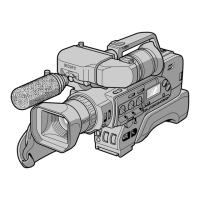
Fig. 5-1-1.
J-9 J-10
J-11
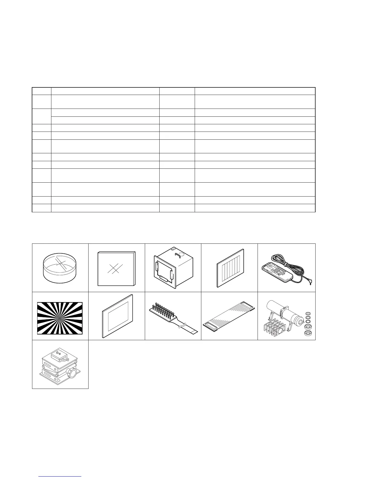
Ref. No.
J-1
J-2
J-3
J-4
J-5
J-6
J-7
J-8
J-9
J-10
J-11
Name
Filter for color temperature correction (C14)
ND filter 1.0
ND filter 0.3
Pattern box PTB-450
Color chart for pattern box
Adjustment remote commander
(RM-95 upgraded) (Note1)
Siemens star chart
Clear chart for pattern box
CPC-13 jig
Extension cable (50P, 0.5mm)
Mini pattern box
Camera table
Parts Code
J-6080-058-A
J-6080-808-A
J-6080-818-A
J-6082-200-A
J-6020-250-A
J-6082-053-B
J-6080-875-A
J-6080-621-A
J-6082-443-A
J-6082-496-A
J-6082-353-B
J-6082-384-A
Usage
Auto white balance adjustment/check
White balance adjustment/check
White balance check
White balance check (2 sheets used)
For checking the flange back
For adjusting the video section
For adjusting the color viewfinder
For extension between the CD-254 board (CN100) and
the VC-242 board (CN025)
For adjusting the flange back
For adjusting the flange back
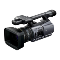
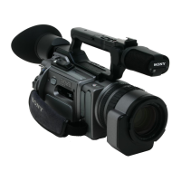
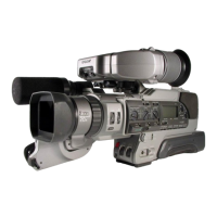
5-1. CAMERA SECTION ADJUSTMENT
1-1. PREPARATIONS BEFORE ADJUSTMENT (CAMERA SECTION)
1-1-1. List of Service Tools
• Oscilloscope • Color monitor • Vectorscope
• Regulated power supply • Digital voltmeter
Note1: If the micro processor IC in the adjustment remote commander is
not the new micro processor (UPD7503G-C56-12), the pages
cannot be switched. In this case, replace with the new micro
processor (8-759-148-35).