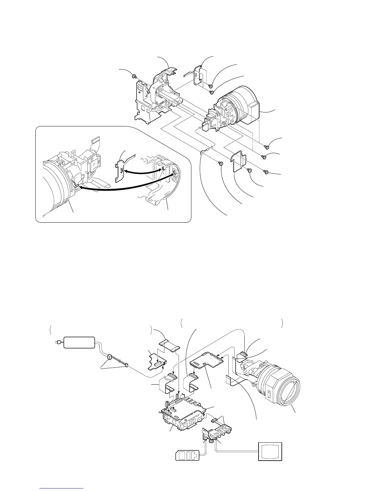
Lens block assembly
2
Tapping screw
(B2
×
5)
3
CCD cover
When installing it.
Align the swich position.
PRECAUTION DURING INSTALLATION
VC-242
Board
LA
-026
B
oard
[SERVICE POSITION TO CHECK THE CAMERA SECTION]
Adjustment remote
commander (RM-95)
AC POWER
ADAPTOR
AC IN
DC-IN
connector (3P)
(1-794-637-11)
DD-138 board
Mechanism deck
VC-242 board
LA-026 board
JK-190 board
Monitor TV
LANC jack
VIDEO jack
Extension cable
(J-6082-496-A) (50P)
CD-254 board (50P)
Flexible board (39P)
(from zoom lens assembly)
Flexible board (27P)
(from VAP assembly)
Lens block assembl
FP-186 flexible board (80P)
Insert the FP-186 flexible board in the opposite
direction to the normal insertion direction.
FP-191 flexible board (60P)
Insert the FP-191 flexible board in the opposite
direction to the normal insertion direction.
Connection to Check the CAMERA Section
To check the CAMERA Section, set the CAMERA to the "forced CAMERA power ON" mode.
Setting the “Forced CAMERA Power ON” mode
1) Select page: 0, address: 01, and set data: 01.
2) Select page: D, address: 10, set data: 01, and press
the PAUSE button of the adjustment remote
commander.
Exiting the “Forced CAMERA Power ON” mode
1) Select page: 0, address: 01, and set data: 01.
2) Select page: D, address: 10, set data: 00, and press
the PAUSE button of the adjustment remote
commander.
3) Select page: 0, address: 01, and set data: 00.