5-7
1-1-3. Precaution
1. Setting the Switch
Unless otherwise specified, set the switches as follows and perform
adjustments without loading cassette.
1. POWER switch (CF-4980 block) .......................... CAMERA
2. DEMO MODE (Menu display) .......................................OFF
3. DIGITAL ZOOM (Menu display) ...................................OFF
4. STEADY SHOT (Menu display) .....................................OFF
5. DISPLAY (Menu display) ................................. V-OUT/LCD
6. DISPLAY (CK-093 board) ............................................... ON
7. AUTO LOCK (MK-014 board) ................................... AUTO
8. ND FILTER (Lens block) ................................................OFF
9. FOCUS switch (FP-188 flexible).......................... MANUAL
10. BACK LIGHT (FP-189 flexible) .....................................OFF
11. SPOT LIGHT (FP-189 flexible) ......................................OFF
12. PICTURE EFFECT (CK-093 board) ...............................OFF
13. DIGITAL EFFECT (CK-093 board)................................OFF
14. ZEBRA (CK-093 board) ..................................................OFF
15. 16 : 9 WIDE (Menu display)............................................OFF
16. AUTO SHUTTER (Menu display) ..................................OFF
17. PROG.SCAN (Menu display)..........................................OFF
2. Order of Adjustments
Basically carry out adjustments in the order given.
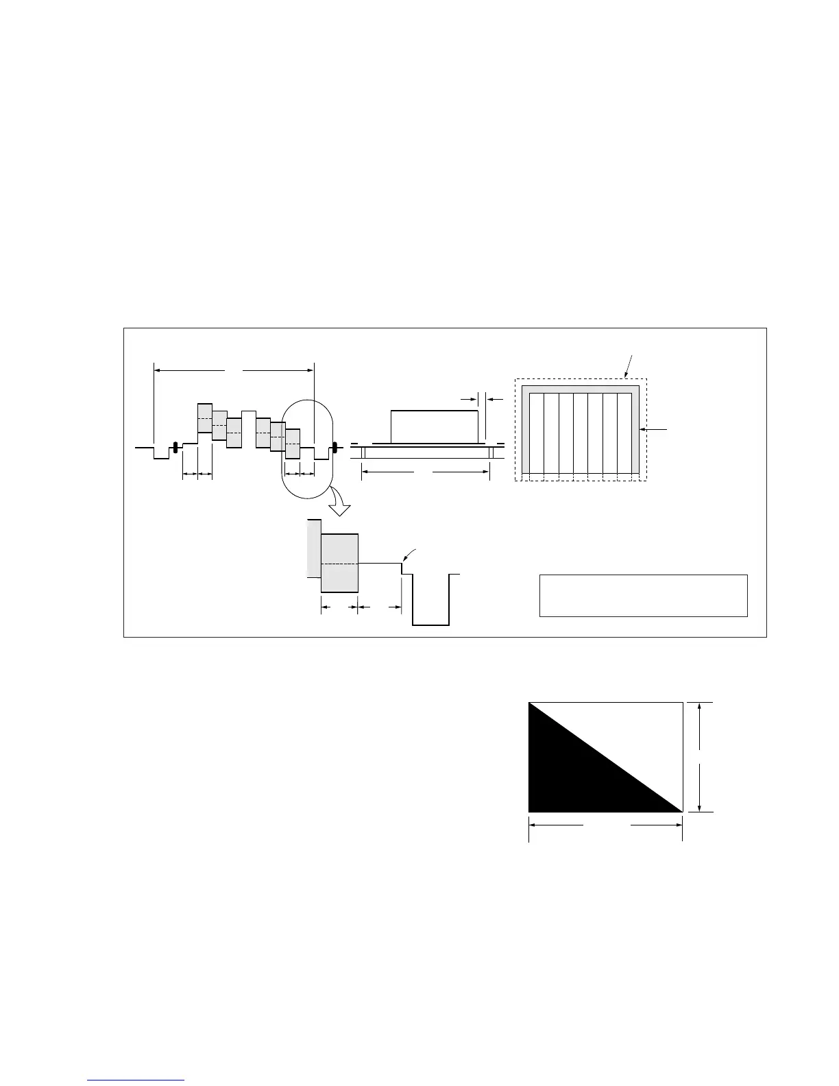
H
A=B
AB B
A
Enlargement
V
0
±
0.1msec
Electronic beam scanning frame
CRT picture frame
B
A
Difference in level
Yellow
Cyan
Green
White
Magenta
Red
Blue
Yellow
Cyan
Green
White
Magenta
Red
Blue
Color bar chart standard picture frame
Fig. a
(Video output terminal
output waveform)
Fig. b (TV monitor picture)
Adjust the camera zoom and direction to
obtain the output waveform shown in Fig. a
and the TV monitor display shown in Fig. b.
Fig. 5-1-4
3. Subjects
1) Color bar chart (Standard picture frame).
When performing adjustments using the color bar chart, adjust
the picture frame as shown in Fig. 5-1-4. (Standard picture
frame)
2) Clear chart (Standard picture frame)
Remove the color bar chart from the pattern box and insert a
clear chart in its place. (Do not perform zoom operations during
this time.)
3) Flange back adjustment chart
Make the chart shown in Fig. 5-1-5 using A0 size (1189 mm ×
841 mm) black and white vellum paper.
White
Black
841m