5-31
2. Bright Adjustment (VC-242 board)
Set the D range of the RGB decoder used to drive the LCD to the
specified value. If deviated, the LCD screen will become blackish
or saturated (whitish).
Mode Camera
Subject Arbitrary
Measurement Point Pin qk of CN007 (EVF VG)
Measuring Instrument Oscilloscope
Adjustment Page D
Adjustment Address 95
Specified Value A = 7.30 ± 0.05V
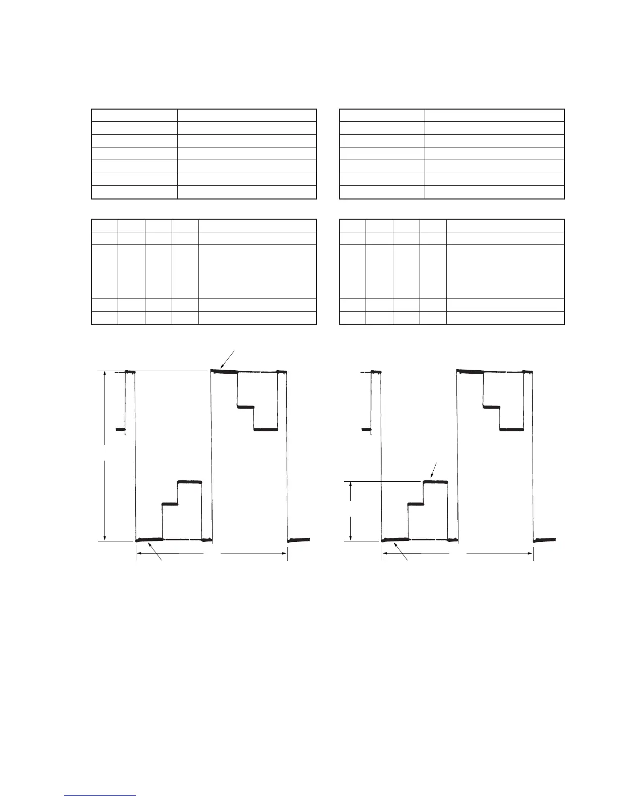
Adjusting method:
Order Page
Address
Data Procedure
1 0 01 01 Set the data.
2 D 95 Change the data and set the
voltage (A) between the reversed
waveform pedestal and non-
reversed waveform pedestal to
the specified value.
3 D 95 Press PAUSE button.
4 0 01 00 Set the data.
3. Contrast Adjustment (VC-242 board)
Set the level of the VIDEO signal for driving the LCD to the specified
value. If deviated, the screen image will be blackish or saturated
(whitish).
Mode Camera
Subject Arbitrary
Measurement Point Pin qk of CN007 (EVF VG)
Measuring Instrument Oscilloscope
Adjustment Page D
Adjustment Address 99
Specified Value A=2.45 ± 0.05V
Adjusting method:
Order Page
Address
Data Procedure
1 0 01 01 Set the data.
2 D 99 Change the data and set the
voltage (A) between the 3 steps
peak and pedestal to the
specified value.
(The data should be “00” to “7F”.)
3 D 99 Press PAUSE button.
4 0 01 00 Set the data.
Pedestal
Pedestal
A
2H
3 steps peak
Pedestal
A
2H
Fig. 5-1-18. Fig. 5-1-19.