5-22
11. MAX GAIN Adjustment
Setting the minimum illumination.
If it is not consistent, the image level required for taking subjects in
low illuminance will not be produced (dark).
Subject Clear chart
(Color bar standard picture frame)
Adjustment Page F
Adjustment Address 2C
Switch setting:
ND FILTER......................................................................OFF
(The data of page: 6, address: 9D is “00”.)
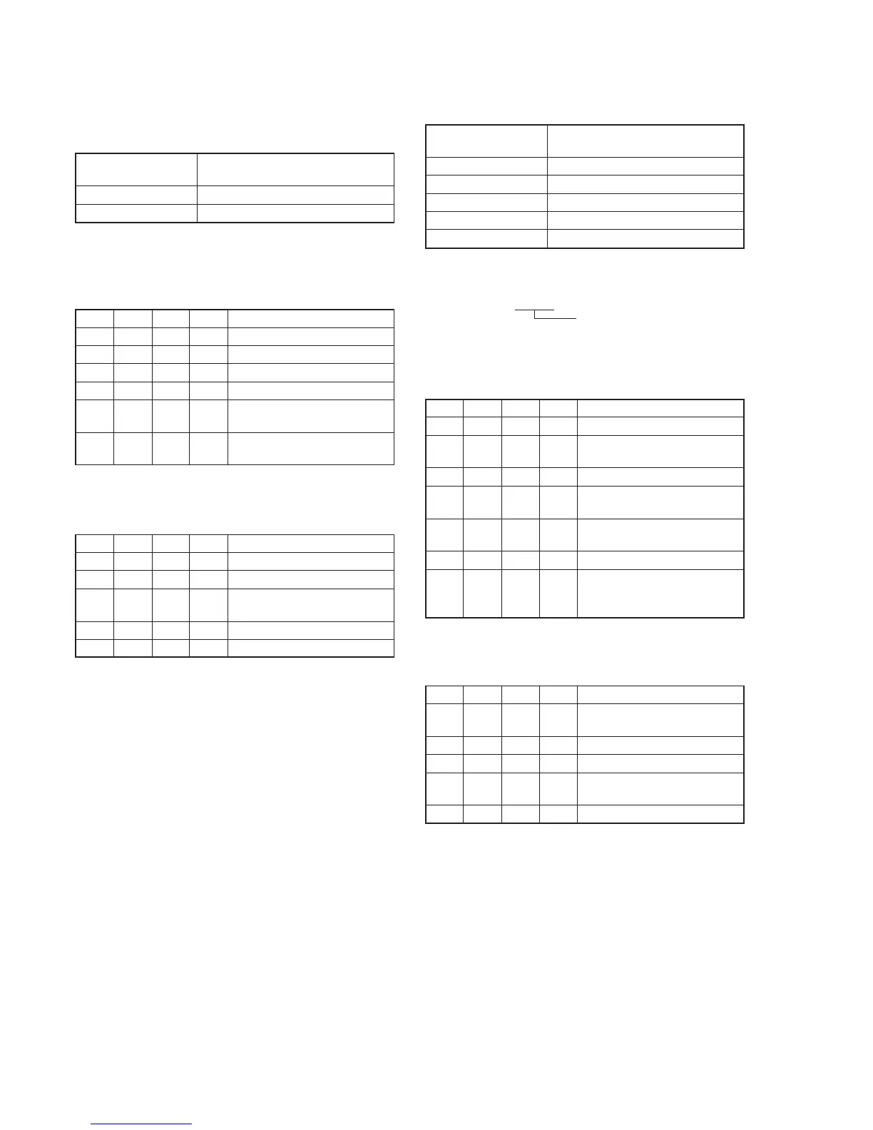
Adjusting method:
Order Page
Address
Data Procedure
1 0 01 01 Set the data.
2 6 02 00 Set the data.
3 6 96 00 Set the data.
4 6 97 5C Set the data.
5 6 01 6F Set the data, and press PAUSE
button. (Note)
6 6 02 Check that the data changes to
“01”.
Note: The adjustment data will be automatically input to page: F, address:
2C.
Processing after Completing Adjustments
Order Page
Address
Data Procedure
1 6 96 00 Set the data.
2 6 97 00 Set the data.
3 6 01 00 Set the data, and press PAUSE
button.
4 6 02 00 Set the data.
5 0 01 00 Set the data.
12. LV Standard Data Input
Adjust the normal coefficient of the light value.
Subject Clear chart
(Color bar standard picture frame)
Measurement Point Display data of page 1 (Note2)
Measuring Instrument Adjustment remote commander
Adjustment Page F
Adjustment Address 3E, 3F
Specified Value 0FE0 to 1020
Note1: Check that the data of page: 6, address: 02 is “00”. If not, turn the
power of the unit OFF/ON.
Note2: Displayed data of page 1 of the adjustment remote commander.
1 : XX : XX
LV data
Switch setting:
ND FILTER......................................................................OFF
(The data of page: 6, address: 9D is “00”.)
Adjusting method:
Order Page
Address
Data Procedure
1 0 01 01 Set the data.
2 F 15 40 Set the data, and press PAUSE
button.
3 Wait for 5 seconds.
4 6 01 0D Set the data, and press PAUSE
button. (Note3)
5 6 02 Check that the data changes to
“01”.
6 6 04 1E Set the data.
7 1 Check that the LV data (Note2)
satisfies the specified value. If
not, repeat from step 2.
Note3: The adjustment data will be automatically input to page: F, address:
3E and 3F.
Processing after Completing Adjustments
Order Page
Address
Data Procedure
1 6 01 00 Set the data, and press PAUSE
button.
2 6 02 00 Set the data.
3 6 04 00 Set the data.
4 F 15 44 Set the data, and press PAUSE
button.
5 0 01 00 Set the data.