5-32
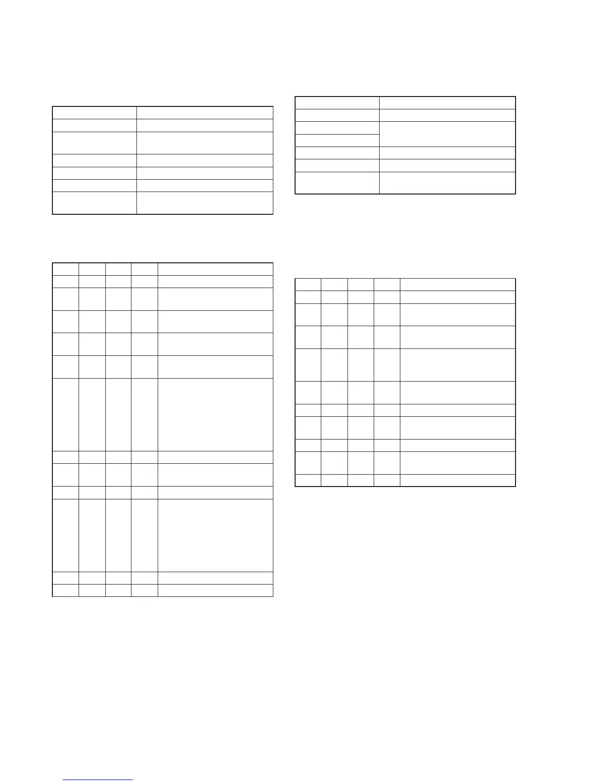
4. Backlight Consumption Current Adjustment
(VC-242 board)
Set the backlight luminance and color temperature.
If deviated, the image may become dark or bright.
Mode Camera
Subject Arbitrary
Measurement Point + Probe: Pin w; of CN007 (
EVF BL+
)
– Probe: Pin qj of CN007 (EVF BL–)
Measuring Instrument Digital voltmeter
Adjustment Page D
Adjustment Address 9C, 9D, 9E, 9F
Specified Value BRIGHT mode : A=37.0 ± 1.5mVdc
NORMAL mode : A=22.0 ± 1.5mVdc
Note1: Perform the adjustment in the following order.
Note2: Adjust 30 seconds after running on the power supply.
Adjusting method:
Order Page
Address
Data Procedure
1 0 01 01 Set the data.
2 D 9C F0 Set the data, and press PAUSE
button.
3 D 9D F0 Set the data, and press PAUSE
button.
4 D 9E 11 Set the data, and press PAUSE
button.
5 D 9F 1F Set the data, and press PAUSE
button.
6 D 9D Change the data and set the
voltage difference (A) between
Pin w; and Pin qj to the
specified value of BRIGHT
mode.
(The data should be “C0” to
“FF”.)
7 D 9D Press PAUSE button.
8 D 9C Set the same data as address:
9D.
9 D 9C Press PAUSE button.
10 D 9E Change the data and set the
voltage difference (A) between
Pin w; and Pin qj to the
specified value of NORMAL
mode.
(The data should be “00” to
“1F”.)
11 D 9E Press PAUSE button.
12 0 01 00 Set the data.
5. White Balance Adjustment (VC-242 board)
Correct the white balance.
If deviated, the reproduction of the EVF screen may degenerate.
Mode Camera
Subject Arbitrary
Measurement Point Check on EVF screen
Measuring Instrument
Adjustment Page D
Adjustment Address 97, 98
Specified Value The EVF screen should not be
colored.
Note1: Check the white balance only when replacing the following parts.
If necessary, adjust them.
1. LCD panel
2. Light induction plate
3. IC1802
Note2: Use the AC power adaptor.
Adjusting method:
Order Page
Address
Data Procedure
1 0 01 01 Set the data.
2 D 97 90 Set the data, and press PAUSE
button.
3 D 98 80 Set the data, and press PAUSE
button.
4 D 98 Check that the EVF screen is not
colored. If not colored, proceed
to step 10.
5 D 97 Change the data so that the EVF
screen is not colored.
6 D 97 Press PAUSE button.
7 D 98 Change the data so that the EVF
screen is not colored.
8 D 98 Press PAUSE button.
9 D 98 If the EVF screen is colored,
repeat steps 5 to 9.
10 0 01 00 Set the data.