5-30
1-4. COLOR ELECTRONIC VIEWFINDER
SYSTEM ADJUSTMENT
Note1: The back light (fluorescent tube) is driven by a high voltage AC
power supply. Therefore, do not touch the back light holder to
avoid electrical shock.
Note2: When replacing the LCD unit, be careful to prevent damages
caused by static electricity.
Note3: As the PANEL CLOSE switch is attached to the cabinet (R), this
cabinet must be attached when performing adjustments.
If you perform the adjustments with cabinet (R) removed, set the
following data.
1) Select page: 2, address: 0E, and set data: 67.
2) Select page: 2, address: 0F, and set data: 01.
Reset the data after completing adjustment.
1) Select page: 2, address: 0E, and set data: 00.
2) Select page: 2, address: 0F, and set data: 00.
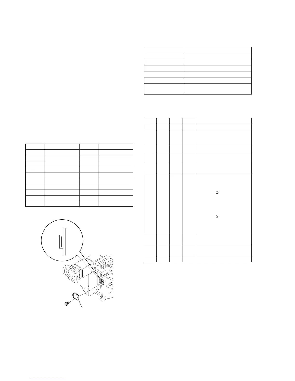
[Adjusting connector]
Most of the measuring points for adjusting the viewfinder system
are concentrated in CN007 of the VC-242 board.
Connect the Measuring Instruments via the CPC-13 jig (J-6082-
433-A).
The following table shows the Pin No. and signal name of CN007.
Table 5-1-7.
1. VCO Adjustment (VC-242 board)
Set the VCO free-run frequency. If deviated, the EVF screen will be
blurred.
Mode Camera
Subject Arbitrary
Measurement Point Pin qg of CN007 (EVF VCO)
Measuring Instrument Frequency counter
Adjustment Page D
Adjustment Address 92, 93
Specified Value f = 15734 ± 30Hz (NTSC)
f = 15625 ± 30Hz (PAL)
Note1: NTSC: DCR-VX2000
PAL: DCR-VX2000E
Adjusting method:
Order Page
Address
Data Procedure
1 0 01 01 Set the data.
2 D 92 Change the data and set the
VCO frequency (f) to the
specified value.
3 D 92 Press PAUSE button.
4 D 92 Read the data, and this data is
named D
92
.
5 Convert D
92
to decimal notation,
and obtain D
92
'. (Note2)
6 Calculate D
93
' using following
equations (Decimal calculation)
NTSC model:
When D
92
' 226
D
93
' = D
92
' + 29
When D
92
' > 226
D
93
' = 255
PAL model:
When D
92
' 29
D
93
' = D
92
' – 29
When D
92
' < 29
D
93
' = 00
7 Convert D
93
' to a hexadecimal
number, and obtain D
93
. (Note2)
8 D 93 D
93
Set the data, and press PAUSE
button.
9 0 01 00 Set the data.
Note2: Refer to “Table 5-4-1. Hexadecimal-decimal Conversion Table”.
Pin No.
1
2
3
4
5
6
7
8
9
10
Signal Name
GND
RF MON
SWP
RF IN/LANC JACK IN
TDO
GND
TCK
TDI
PANEL COM
TMS
Pin No.
11
12
13
14
15
16
17
18
19
20
Signal Name
H START
XHD/PSIG
EVF VB
EVF VR
EVF VCO
GND
EVF BL –
EVF VG
LANC SIG
EVF BL +
Remove the CPC cover
CN007
20
1
Fig. 5-1-17.