5-40
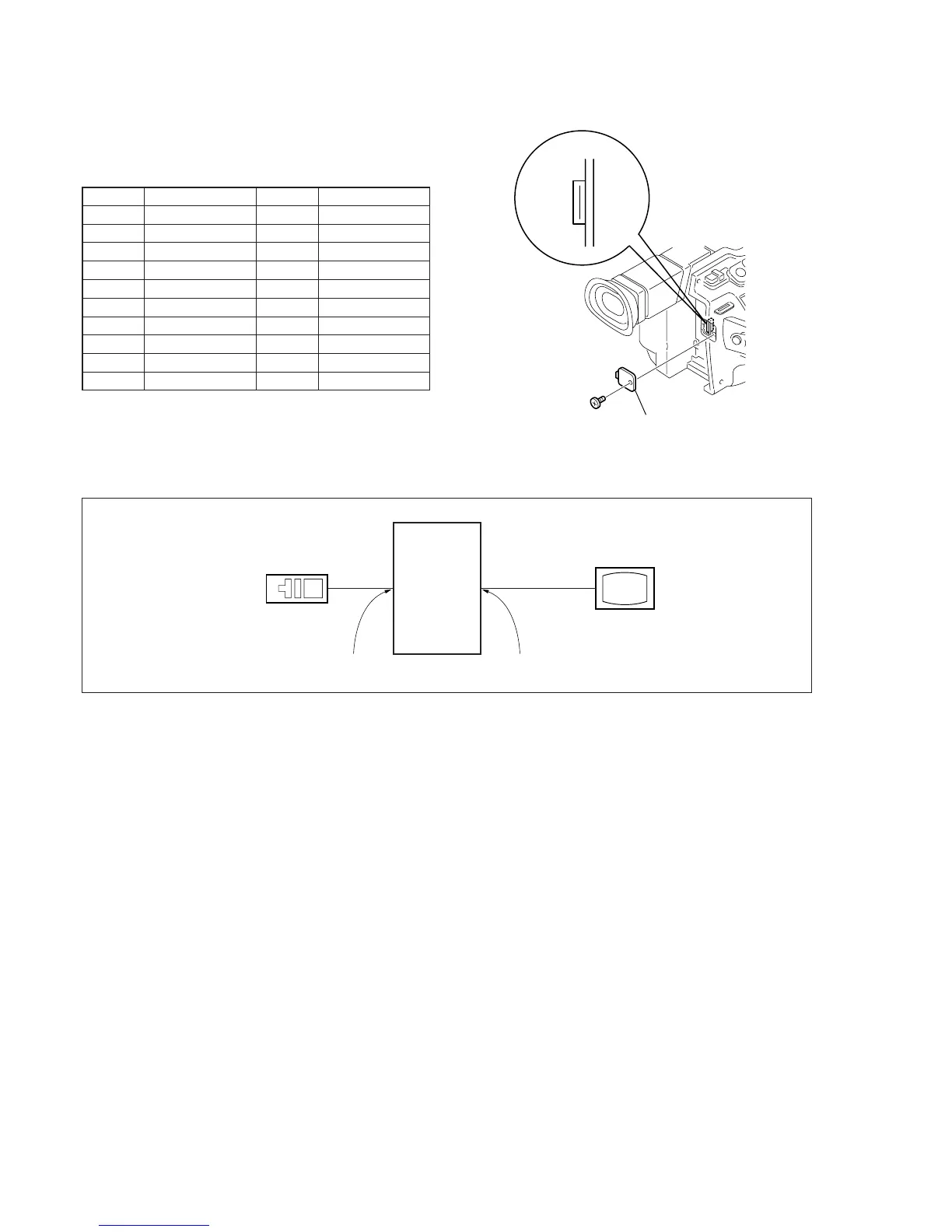
Fig. 5-3-2.
Adjustment
remote
commander
LANC jack
Main unit
VIDEO jack
TV monitor
Fig. 5-3-1
3-1-3. Adjusting Connectors
Some of the adjusting points of the video section are concentrated
at VC-242 board CN007. Connect the measuring instruments via
the CPC-13 jig (J-6082-443-A). The following table lists the pin
numbers and signal names of CN007.
Table 5-3-1.
3-1-4. Connecting the Equipment
Connect the measuring instruments as shown in Fig. 5-3-2, and
perform the adjustments.
Pin No.
1
2
3
4
5
6
7
8
9
10
Signal Name
GND
RF MON
SWP
RF IN/LANC JACK IN
TDO
GND
TCK
TDI
PANEL COM
TMS
Pin No.
11
12
13
14
15
16
17
18
19
20
Signal Name
H START
XHD/PSIG
EVF VB
EVF VR
EVF VCO
GND
EVF BL –
EVF VG
LANC SIG
EVF BL +
Remove the CPC cover
CN007
20
1