2-1
SECTION 2
DISASSEMBLY
DCR-VX2000/VX2000E
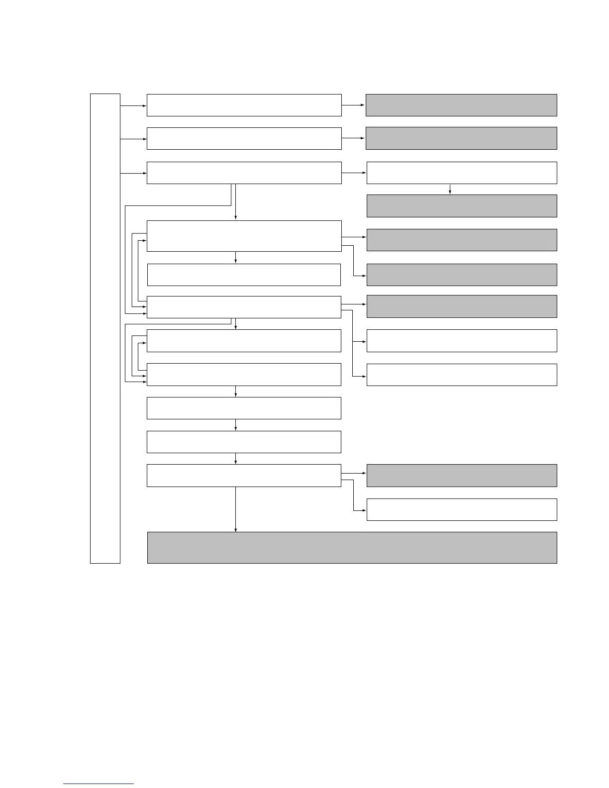
The following flow chart shows the disassembly procedure.
DCR-VX2000/VX2000E
2-2. EVF section (LB-065 board)
2-5. Cabinet (L) block assembly, Mechanism deck,
VC-242, DD-138, JK-190 boards
(for force eject of cassette and VTR section check)
2-4. FK-076, MA-386, MI-038, FT-090 boards
2-13. Control switch block (PS-4980),
Control switch block (CF-4980)
FK-076, MA-386, MI-038, FT-090 boards
service position
Mechanism deck service position-1
Service position to check the VTR section
2-12. CD-254, SE-108 boards, Zoom lens assembly
2-1. LCD section
(HL-011, PD-126 boards, Inverter transformer unit)
2-3. (Upper) handle block assembly
2-6. Cabinet (R) block assembly
2-7. Cabinet bottom (D) assembly 2-14. CK-093 board
2-15. Control switch block (ED-4980),
Hinge assembly
2-8. Battery panel block assembly
(MK-014, KP-010, MS-049 boards)
2-9. EVF block assembly
2-10. LA-026, DD-138, VC-242, JK-190 boards,
Mechanism deck
2-11. Lens block assembly, Center frame assembly
HL-011, PD-126 boards service position
[Connection diagram for service position (Mainly for voltage measurement and check)]
(CK-093, VC-242, JK-190, CD-254, DD-138, LA-026, KP-010, MK-014, MS-049 boards, Mechanism deck-2)
LB-065 board service position
CK-093 board service position
Service position to check the camera section