1-1. DSR-2000
Location and Function of Parts
Chapter 1 Overview
14
Chapter 1 Overview
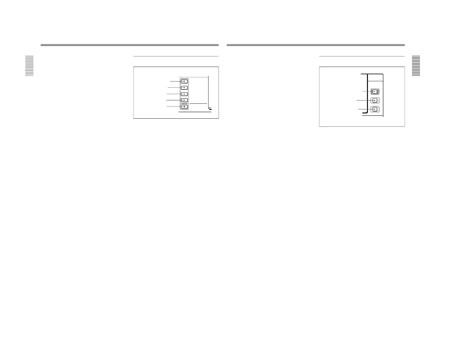
1 INPUT display
Indicates the input signal selected with the SDTI/
i.LINK button in the input selection section.
V:SDTI: Digital video signal in SDTI(QSDI) format
In this mode, you can select any audio input,
though the video signal is recorded with a delay of
two frames with respect to the audio input.
SDTI: Digital video and audio signals in
SDTI(QSDI) format
i.LINK: Digital video and audio signals in DV
format, using i.LINK technology
2 INPUT VIDEO display
Indicates the input video signal selected with the
VIDEO IN button in the input selection section.
COMPOSITE: Composite video signal
Y-R, B: Y, R−Y and B−Y component video signals
S VIDEO: S-video signal
SDI: SDI video signal
SG: Video test signal
3 AUDIO CH1, 1/2 display
Indicates the input audio signal selected with the CH1,
1/2 button in the input selection section.
ANALOG: Analog audio signal
AES/EBU: Digital audio signal in AES/EBU format
SDI: SDI audio signal
SG: Audio test signal
4 AUDIO CH2, 3/4 display
Indicates the input audio signal selected with the CH2,
3/4 button in the input selection section. The
indications available are the same as for the AUDIO
CH1, 1/2 display described above.
5 PB FS (playback audio sampling frequency)
display
Indicates the sampling frequency (48 kHz, 44.1 kHz or
32 kHz) at which audio is recorded on tape.
6 REC MODE (audio recording mode) display
Indicates the audio recording mode (2CH or 4CH)
selected with extended menu item 818.
2 Input selection section
1 SDTI/i.LINK (SDTI(QSDI) interface/i.LINK
selection) button
Each press of this button cycles through the following
input signal selection options.
• Digital video signal in SDTI(QSDI) format input to
the SDTI(QSDI) INPUT connector
When this is selected, use the CH1, 1/2 button and
CH2, 3/4 button to select the required input audio
signals.
• Digital video and audio signals in SDTI(QSDI)
format input to the SDTI(QSDI) INPUT connector
• Digital video and audio signals in DV format, using
i.LINK technology, input to the i.LINK connector
(available when the optional DSBK-190 i.LINK/DV
Input/Output Board is installed)
In the input selection/audio mode display section, the
INPUT display shows the selection made with this
button.
2 VIDEO IN button
Each press of this button cycles through the following
input video signal selection options.
• Composite video signal input to the VIDEO IN
connectors.
• Component video signals input to the COMPONENT
VIDEO Y/R−Y/B−Y IN connectors
• S-video signal input to the S VIDEO IN connector
• SDI video signal input to the SDI INPUT connector
• Video test signal (selected with extended menu item
710) generated by the internal signal generator
In the input selection/audio mode display section, the
INPUT VIDEO display shows the selection made with
this button.
Chapter 1 Overview
Chapter 1 Overview
15
3 CH1, 1/2 (audio channel 1 or 1/2) button
Each press of this button cycles through the following
input audio signal selection options for audio channel 1
(when in 2-channel mode) or for audio channels 1 and
2 (when in 4-channel mode).
•Analog audio signal(s) input to the AUDIO IN CH-1
connector (when in 2-channel mode) or AUDIO IN
CH-1 and CH-2 connectors (when in 4-channel
mode).
•Digital audio signal in AES/EBU format input to the
DIGITAL AUDIO (AES/EBU) CH-1/2 connector
•SDI audio signal input to the SDI INPUT connector
•Audio test signal (selected with extended menu item
808) generated by the internal signal generator
In the input selection/audio mode display section, the
AUDIO CH1, 1/2 display shows the selection made
with this button.
4 CH2, 3/4 (audio channel 2 or 3/4) button
Each press of this button cycles through the input audio
signal selection options for audio channel 2 (when in 2-
channel mode) or for audio channels 3 and 4 (when in
4-channel mode) The input audio signal selection
options corresponding to those for the CH1, 1/2 button
described above are available.
In the input selection/audio mode display section, the
AUDIO CH2, 3/4 display shows the selection made
with this button.
5 MIXING (mixing setting on/off) button
This enables (ON) or disables (OFF) the setting for
audio input mixing made with extended menu item
819.
If the selected signal (except for analog audio) is not
supplied to the appropriate connector, the
corresponding indicator in the input selection/audio
mode display section flashes.
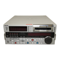
3 Remote control setting section
1 REMOTE button
When remote-controlling this unit from the unit
connected to the REMOTE-IN, REMOTE-OUT or
i.LINK connector, press this button, turning it on.
2 9PIN button
When carrying out remote control between this unit
and the unit connected to the REMOTE-IN or
REMOTE-OUT connector, press this button, turning it
on.
3 i.LINK button
When carrying out remote control between this unit
and the unit connected to the i.LINK connector, press
this button, turning it on.
This button is effective only when the optional DSBK-
190 i.LINK/DV Input/Output Board is installed.