1-9
DSR-2000/2000P
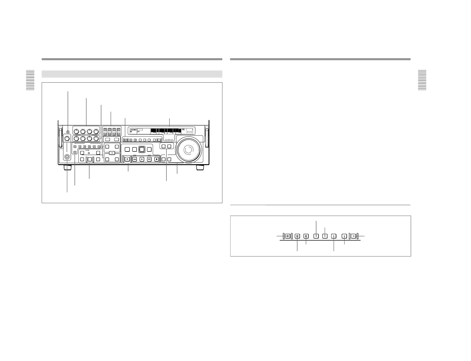
1-1. DSR-2000
Location and Function of Parts
Chapter 1 Overview
16
Chapter 1 Overview
Lower Control Panel
FULL/FINE
PHONE LEVEL
CH-1
REC
PB
ASSEMBLE
HEADPHONES
PREVIEW REVIEW
AUTO
DMC EDIT
DELETE
MEMORY
VIDEO
INSERT
CH-1 CH-2 CH-3 CH-4 TC
CH-2 CH-3 CH-4
CH-4CH-3CH-2CH-1
L
R
TRIM
PULL FOR VARIABLE
IN
OUT
IN OUT
AUDIO
REC
STANDBY
EJECT REW PLAY F FWD STOP
SEARCH VARIABLE
PREROLL
EDIT
PLAYER RECORDER
ENTRY SHIFT
LIST MARK
PREREAD PB/EE PB MENU SET HOLD
COUNTER SEL
RESET
CHANNEL
CONDITION
-+
MONITOR SELECT
METER
EDIT
ClipLink
LP
VITC
INHIBIT
KEY INHIBIT SERVO
SHUTTLE
JOG
COUNTER
HOURS MINUTES SECONDS FRAMES
REPEAT
NOT
EDITABLE
REC
U-BIT TC
1 METER FULL/FINE button
2 REC controls
3 PB controls
4 MONITOR SELECT buttons
5 HEADPHONES jack and PHONE LEVEL control
1 Monitor/menu/display setting
section
(see page 17)
2 Display section
(see page 18)
3 Edit mode setting section
(see page 20)
4 Editing control section
(see page 21)
5 Tape transport control
section
(see page 22)
6 Search control section
(see page 23)
1 METER FULL/FINE button
This switches the display mode of the audio level
meters in the upper control panel as follows:
FULL: In this mode the segment of the display
corresponding to the current audio level and all
lower segments light. A marker indicating the
reference level (set with extended menu item 811)
also appears.
FINE: The display is enlarged, with a step of 0.25 dB
with respect to the reference level of 0 dB.
In this mode only the segment of the display
corresponding to the current audio level lights. If
the audio level exceeds the maximum display
level, the top segment flashes, and if the audio
level goes below the minimum display level, the
bottom segment flashes.
2 REC (recording) controls
These individually adjust the recording levels on
channels 1 to 4.
To set the recording level, put the unit in E-E mode,
pull out the control knobs and adjust the level while
watching the level meters.
When the control knobs are pushed in, the recording
levels return to the preset levels and cannot be
adjusted.
For details of selecting the E-E mode, see the description of
the REC button in the tape transport control section (see
page 22) and the PB/EE button in the monitor/menu/display
setting section (see page 17).
6 PLAYER button and RECORDER button
Chapter 1 Overview
Chapter 1 Overview
17
3 PB (playback) controls
These adjust individually the playback levels on
channels 1 to 4.
During playback, pull out the control knobs and adjust
the level while watching the level meters.
When the control knobs are pushed in, the playback
levels return to the preset levels, and cannot be
adjusted.
4 MONITOR SELECT buttons
There are four buttons CH-1 to CH-4 (channels 1 to 4)
in each of the upper (L) and lower (R) rows. Use these
buttons to select the channels for audio output via the
HEADPHONES connector on the lower control panel
and the MONITOR AUDIO connector on the
connector panel.
The HEADPHONES connector outputs stereo sound
(L and R) and the MONITOR AUDIO connector
outputs monaural sound (L and R mixed).
You can select two or more channels in either row by
pressing the buttons for the desired channels
simultaneously. The sounds of the channels selected in
the row are mixed.
In 2-channel audio recording mode (selected with
extended menu item 818), it is possible to use the
AUDIO OUT CH-3 and AUDIO OUT CH-4
connectors for monitor audio output for channels 1 and
2, respectively (use extended menu item 820).
5 HEADPHONES jack and PHONE LEVEL
control
Connect stereo headphones with an impedance of 8
ohms to monitor the sound during recording, playback
and editing.
The PHONE LEVEL control knob adjusts the volume.
6 PLAYER button and RECORDER button
When you carry out editing using a VCR connected to
the REMOTE-IN or REMOTE-OUT connector as the
player and this unit as the recorder, these buttons select
which VCR the editing control buttons and tape
transport buttons on this unit control.
PLAYER: The editing control buttons and tape
transport buttons on this unit control the external
player VCR.
RECORDER: The editing control buttons and tape
transport buttons on this unit control the recorder
(this unit).
When this unit is being used in standalone mode,
neither button functions.
1 Monitor/menu/display setting section
PREREAD PB/EE PB MENU SET HOLD
COUNTER SEL
RESET
1 PREREAD button
2 MENU button
3 SET button
4 RESET button
5 PB/EE button
6 PB button
7 HOLD button
8 COUNTER SEL button
1 PREREAD button
When this is lit, a preread (read-before-write) is carried
out in insert editing.
For details of preread editing, see the section
“Preread
Editing” (page 87).
2 MENU button
Use this button for setup menu operations.
Pressing this button, turning it on, shows setup menus
in the time counter display (see page 18).
Press the button once more to exit from the menu
display.
For details of setup menu operations, see Chapter 6
“Setup
Menu” (page 107).
3 SET button
Use this button for setting time code and user bit
values and in setup menu operations.
For details of setting time code and user bit values see
Chapter 2 “Setting/Displaying Time Data and Text
Information” (page 35).