1-1. DSR-2000
Location and Function of Parts
Chapter 1 Overview
18
Chapter 1 Overview
4 RESET button
To reset a time counter value (COUNTER) shown in
the time counter display, press this button.
Resetting the COUNTER value erases all edit points.
This button is also used for setting time code and user
bit values and in setup menu operations.
5 PB/EE (playback/E-E) button
To select E-E mode input signals for the video/audio
signals output during fast forward, rewind, still, and
standby, press this button, turning it on.
Either one of this button and the PB button is always
lit.
6 PB (playback) button
To select playback signals for the video/audio signals
output during fast forward, rewind, still, and standby,
press this button, turning it on.
Either one of this button and the PB/EE button is
always lit.
7 HOLD button
To stop updating of the time code or user bit value in
the time counter display (that is, to hold the display),
press this button, turning it on. To set a time code or
user bit value, first press this button to hold the value.
8 COUNTER SEL (select) button
This switches the value shown in the time counter
display in the following sequence: COUNTER, TC, U-
BIT.
Time counter display selection
a) The selection of TC or VITC is made by the TC SELECT
switch on the subsidiary control panel.
Selection Value displayed
COUNTER Tape running time (hours, minutes,
seconds, frames)
TC
Playback time code read by the internal
time code reader or time code being
recorded.
a)
U-BIT User bit value inserted in the playback time
code or time code being recorded.
a)
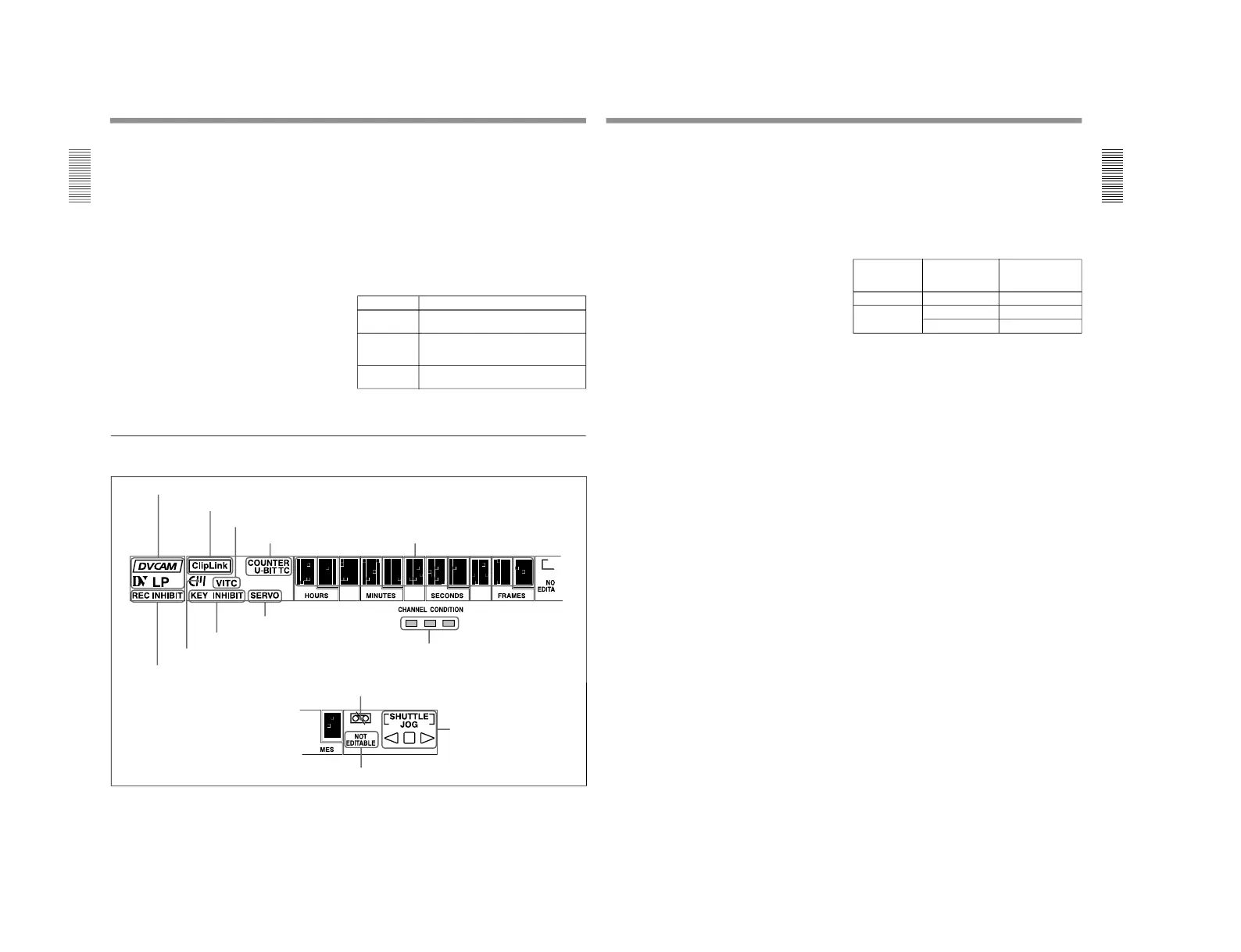
2 Display section
1 Recording/playback format indicators
2 ClipLink indicator
3 VITC indicator
4 Time data type indicators
5 Time counter display
6 REC INHIBIT indicator
7 Cassette memory indicator
8 KEY INHIBIT indicator
9 SERVO indicator
!º CHANNEL CONDITION indicator
!¡Tape end alarm indicator
!™ SHUTTLE/JOG indicators
!£ NOT EDITABLE indicator
Chapter 1 Overview
Chapter 1 Overview
19
1 Recording/playback format indicators
DVCAM: This lights when a tape recorded in
DVCAM format is played back.
DV: This lights when a tape recorded in consumer
DV format is played back.
LP: This lights when a tape recorded in LP mode is
played back.
When a tape recorded in DVCPRO (25) format or any
other format than those mentioned above is played
back, none of the above indicators lights.
2 ClipLink indicator
Lights when a cassette is loaded on which ClipLink
log data is stored in the cassette memory.
For details of ClipLink log data, see the appendix
“ClipLink
Guide” (page 147).
3 VITC indicator
Regardless of the data shown in the time counter
display, this indicator lights when VITC in the signal
played back or in the input video signal (in E-E mode)
is being read.
4 Time data type indicators
One of the three indicators (COUNTER, U-BIT, and
TC) lights to indicate the type of time data currently
shown in the time counter display.
COUNTER: Count value of the time counter
U-BIT: User bit data
TC: SMPTE time code (DSR-2000) or EBU time
code (DSR-2000P)
5 Time counter display
Indicates the count value of the time counter, time
code, or user bit data depending on the settings of the
COUNTER SEL button in the monitor/menu/display
setting section and the TC SELECT switch on the
subsidiary control panel.
Also used to display edit point values, edit duration
values, error messages and setup menu data.
6 REC (recording) INHIBIT indicator
This indicator is on or off according to the
combination of the setting of the REC INHIBIT switch
on the subsidiary control panel and the REC/SAVE
switch on the loaded cassette, as shown in the
following table. When this indicator is on, recording
on tape is prohibited.
REC INHIBIT indicator indications
a) It is possible to make a setting (extended menu item 107)
so that in this case the indicator flashes.
7 Cassette memory indicator
Lights when a cassette provided with a memory chip
(“cassette memory”) is loaded.
8 KEY INHIBIT indicator
This indicator lights when the KEY INHIBIT switch
on the subsidiary control panel is set to ON.
The buttons/switches to be operable even when this
indicator is on can be determined using extended menu
item 118.
9 SERVO indicator
When the drum servo and capstan servo are locked
1)
,
this indicator lights.
!º CHANNEL CONDITION indicator
This three-color indicator shows the state of the
playback signal.
Green: The state of the playback signal is good.
Yellow: The playback signal is somewhat
deteriorated, but playback is possible.
Red: The playback signal is deteriorated.
When the red indicator remains on, head cleaning
or an internal inspection is necessary.
REC INHIBIT
switch position
State of the REC/
SAVE switch on
the cassette
REC INHIBIT
indicator state
ON SAVE/REC Lit
OFF SAVE Lit
a)
REC Off
1) Servo lock: This refers to the synchronization of the
phase of the drum rotation and the reference signal for the
tape transport position, so that the video heads can trace
the same pattern on the tape for playback or recording.
...............................................................................................................................
..........................................................