1-1. DSR-2000
Chapter 7 Connections and
Settings
130
Chapter 7 Connections and Settings
Settings Required When Connecting an External
Editing Control Unit
When connecting an external editing control unit to
this unit and using this unit as a recorder, make the
following timecode settings on this unit and VCR
constant and DIP switch settings on the editing control
unit.
Timecode Settings on This Unit
Make the following time code settings for this unit.
Settings on Editing Control Units
Make the following settings according to the editor
model.
For FXE-100/120 (NTSC)
Set the VCR constants as follows.
For FXE-100P/120P (PAL)
Set the VCR constants as follows.
For BVE-910/2000
Set the VCR constants as follows.
•When using the DSR-2000 (NTSC)
•When using the DSR-2000P (PAL)
Control Setting
INT/EXT–PRESET/REGEN
switch
INT–PRESET (right position)
FREE RUN/REC RUN switch FREE RUN
For RM-450 (NTSC)
Set the VCR constants as follows.
•Left DIP switch
•Right DIP switch
For RM-450CE (PAL)
Set the VCR constants as follows.
•Left DIP switch
•Right DIP switch
For BVE-800
Set the VCR constants as follows.
When using the DSR-2000 (NTSC)
•SW2
•SW3
When using the DSR-2000P (PAL)
•SW2
•SW3
For PVE-500
Use the factory settings as they are.
Switch No.
76543210
Setting OFF ——OFF ————
Switch No.
12345678
Setting ON OFF ON ON — ON ON —
Switch No.
76543210
Setting OFF — OFF ON OFF OFF ON ON
Switch No.
76543210
Setting OFF ——OFF ————
Switch No.
76543210
Setting ON — OFF ON OFF OFF ON ON
Switch No.
12345678
Setting ON OFF ON ON — ON ON —
Switch No.
12345678
Setting ON ON ON OFF — ON OFF OFF
Switch No.
12345678
Setting OFF OFF OFF ON — ON OFF OFF
Byte No.
123456789
10 11 12 13 14 15
Setting 80 14 00 96 05 05 03 80 0A 08 FE 00 80 5A FF
Byte No.
123456789
10 11 12 13 14 15
Setting 81 14 00 7D 05 05 02 80 0A 07 FE 00 80 4C FF
Byte No.
Block 1 Block 2
123456789
10 11 12 13 14 15
Setting 80 14 00 96 05 05 03 80 0A 08 FE 00 80 5A FF
Byte No.
Block 1 Block 2
123456789
10 11 12 13 14 15
Setting 81 14 00 7D 05 05 02 80 0A 07 FE 00 80 4C FF
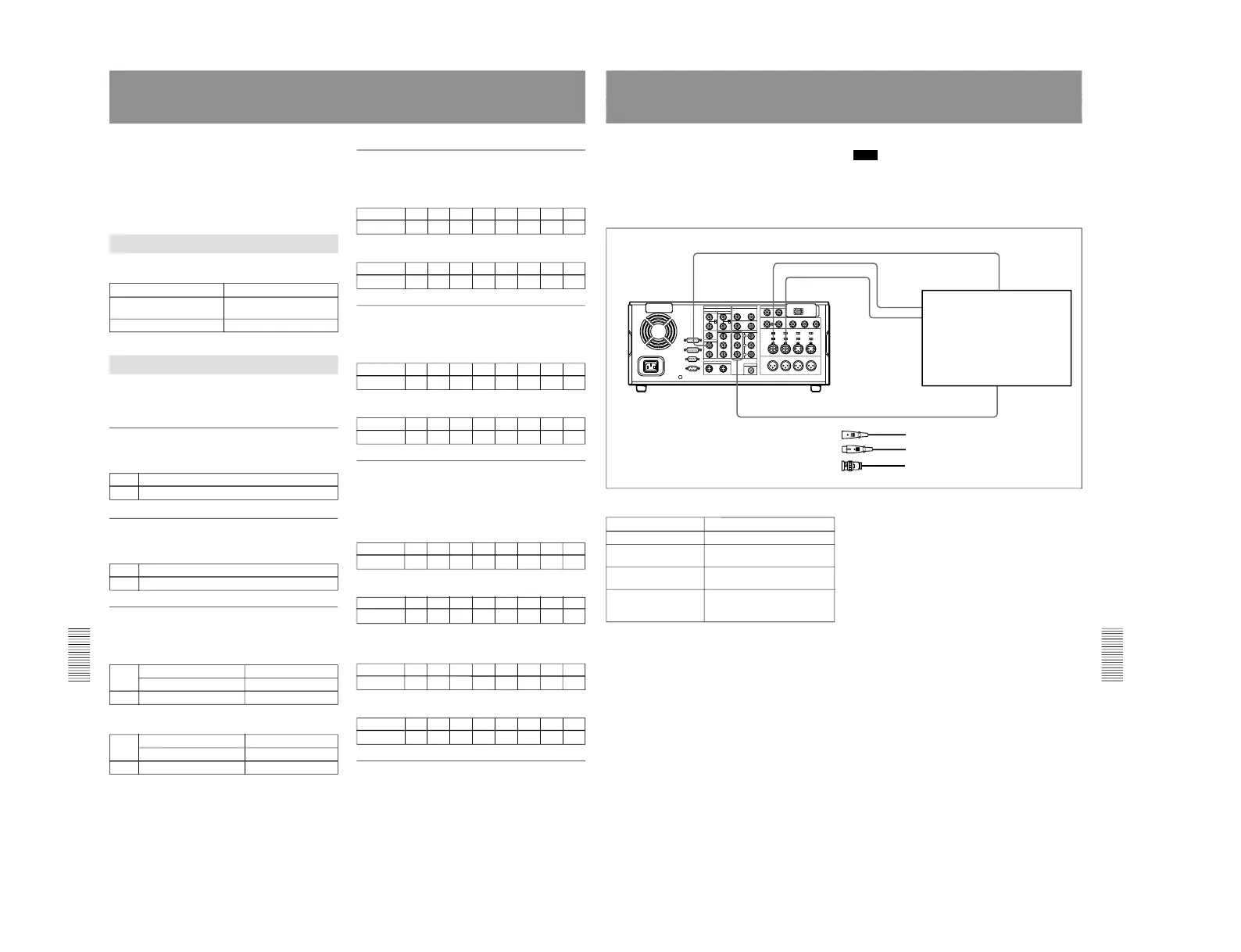
Connections for Component Analog Recording
The following shows connections for a system in
which analog playback signals from another recorder
or player are recorded on the DSR-2000/2000P. In this
system, the video signals are analog component signals
and the audio signals are recorded from audio channels
1 and 2.
Note
In this case, the DSBK-170 Analog Component Iuput/
Output Board is required.
DSR-2000/2000P (recorder) settings
Control
Setting
Videocassette recorder/
player such as
UVW-1600/1600P
DSR-2000/2000P
(recorder)
1 Cable with XLR connectors
(not supplied)
2 75 Ω coaxial cable (not supplied)
REMOTE button Unlit
VIDEO IN button (input
selection section)
Y–R, B
CH1,1/2 button and
CH2,3/4 button
ANALOG
AUDIO IN LEVEL/600Ω
switch (connector panel)
Normally, +4 dBm, 600Ω (HIGH-
ON)