1-67
DSR-2000/2000P
1-1. DSR-2000
Chapter 7 Connections and
Settings
132
Chapter 7 Connections and Settings
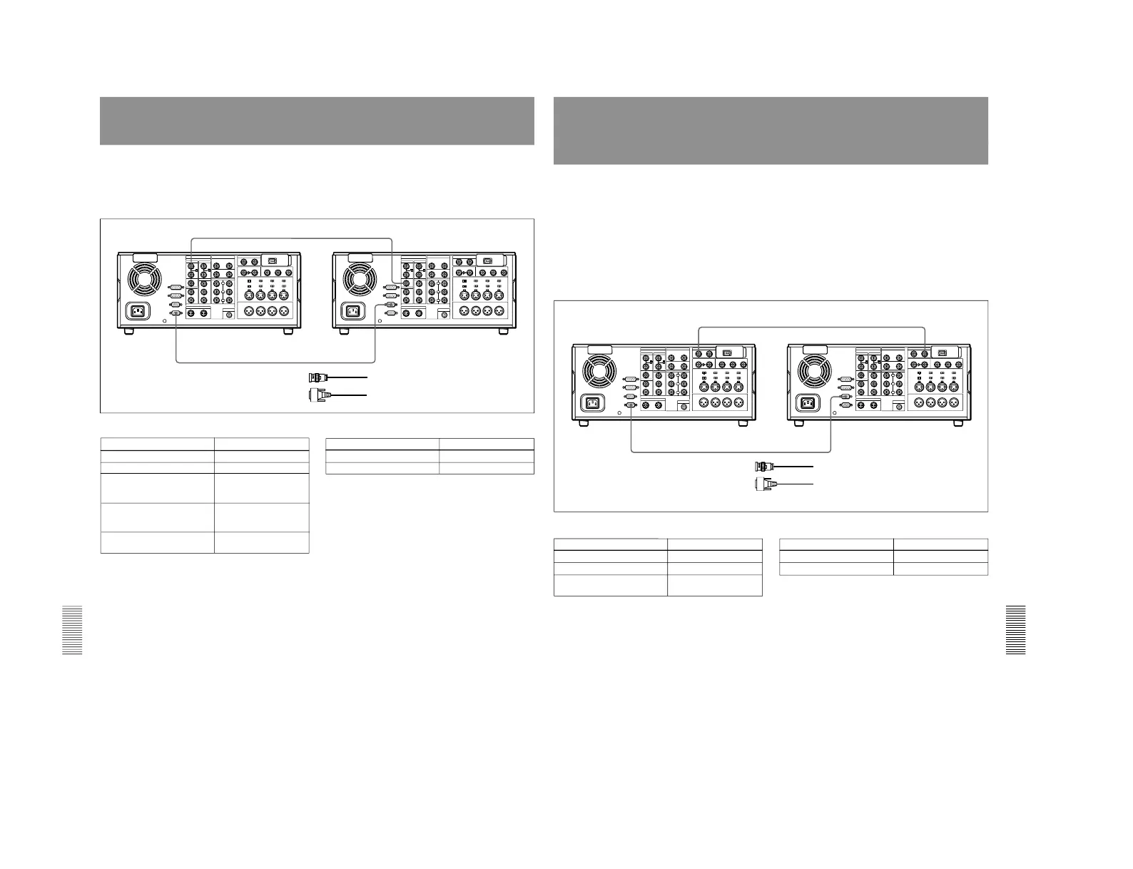
Connections for Two-Unit Synchronous Playback
The following shows connections for synchronous
playback using two DSR-2000/2000P units.
In the following, the controlling unit is referred to as
the recorder and the controlled unit as the player.
For information about how to carry out two-unit
synchronous playback, see the section
“Synchronous
Playback” on page 59.
REF.VIDEO OUT
REMOTE-IN
REMOTE-OUT
REF.VIDEO IN
1
2
DSR-2000/2000P (player) settings
Control Setting
REMOTE button Lit
9PIN button Lit
DSR-2000/2000P (recorder) settings
Control
Setting
REMOTE button Unlit
Setup menu item 004 ON (Synchronize.)
OFF (Do not
synchronize.)
Setup menu item 305
(When synchronizing,
synchronization accuracy)
ACCUR (±0 frame)
ROUGH (±1 frame)
REF. VIDEO IN 75 Ω
termination switch
ON
DSR-2000/2000P (recorder)
DSR-2000/2000P (player)
1 75 Ω coaxial cable (not supplied)
2 RCC-5G 9-pin remote control cable (supplied)
9PIN button Lit
Chapter 7 Connections and
Settings
Chapter 7 Connections and Settings
133
Connections for Digitally Dubbing Signals in
DVCAM Format
(Optional DSBK-190 Required When
Using i.LINK Interface)
You can use this unit to digitally dub signals in
DVCAM format automatically from the beginning of
the tape to the end, through an i.LINK or SDTI(QSDI)
interface.
For information about how to carry out digital dubbing, see
the section “Digitally Dubbing Signals in DVCAM Format
”
(page 61).
Connecting two DSR-2000/2000P units using
the i.LINK interface (DSBK-190 i.LINK/DV
Input/Output Board)
Make the same connections and settings as described
in the section “Connections for Cut Editing Using
i.LINK Interface”
(page 125).
DSR-2000/2000P (player) settings
Control Setting
REMOTE button Lit
9PIN button Lit
DSR-2000/2000P (recorder) settings
Control Setting
REMOTE button Unlit
9PIN button Lit
SDTI/i.LINK button SDTI
(input selection section)
SDTI(QSDI) OUTPUTSDTI(QSDI) INPUT
REMOTE-INREMOTE-OUT
1
2
DSR-2000/2000P (player)
1 75 Ω coaxial cable (not supplied)
2 RCC-5G 9-pin remote control cable (supplied)
DSR-2000/2000P (recorder)
Connecting two DSR-2000/2000P units using the SDTI(QSDI) interface
When connecting this unit with a DSR-60/60P/
80/80P/85/85P/1000-series/1000P-series unit
using the SDTI(QSDI) interface
Replace the DSR-2000/2000P (player) shown in the
above diagram with a DSR-60/60P/80/80P/85/85P/
1000-series/1000P-series unit and make the same
connections as shown above.
The SDTI(QSDI) interface connector of the DSR-60/
60P/80/80P/85/85P is marked
“QSDI(OUTPUT)
”.