1-1. DSR-2000
Chapter 8 Maintenance and Troubleshooting
138
Chapter 8 Maintenance and Troubleshooting
Input problems
a) In this state, an alarm message appears in the display section and on the monitor screen.
Monitor problems
Audio problems
Symptom Cause Remedy
Data is not superimposed on
the monitor screen.
The CHARACTER switch on the
subsidiary control panel is set to OFF.
Set the CHARACTER switch on the subsidiary
control panel to ON.
The monitor is not connected to the
VIDEO OUT 3 (SUPER) or SDI OUTPUT
3 (SUPER) connector of this unit.
Connect the monitor to the VIDEO OUT 3
(SUPER) or SDI OUTPUT 3 (SUPER) connector.
(You must make this connection to display any
type of text on the monitor.)
The image on the monitor
screen is too bright.
The 75 Ω termination switch for video
input on the monitor is in the OFF
position or a 75 Ω terminator is not fitted
to its video input connector.
Set the 75 Ω termination switch to ON or connect
a terminator.
The image on the monitor
screen is too dark.
In a video signal loop-through connection
of video monitors, 75 Ω termination
switches for video input on monitors
other than the loop-end monitor are in
the ON position.
Set the 75 Ω termination switches to OFF on all
monitors other than the loop-end monitor .
The image is too dark when
recording a composite video
signal.
Symptom Cause Remedy
Turning the REC controls does
not change the audio input
levels.
The REC controls are pushed in. Pull out the REC controls.
Turning the PB controls does
not change the playback audio
output levels.
The PB controls are pushed in. Pull out the PB controls.
Troubleshooting
Symptom Cause Remedy
It is not possible to record an
SDTI signal.
No SDTI signal is input to the unit.
a)
Connect an SDTI (QSDI) signal to the SDTI
(QSDI) INPUT connector.
Chapter 8 Maintenance and Troubleshooting
Chapter 8 Maintenance and Troubleshooting
139
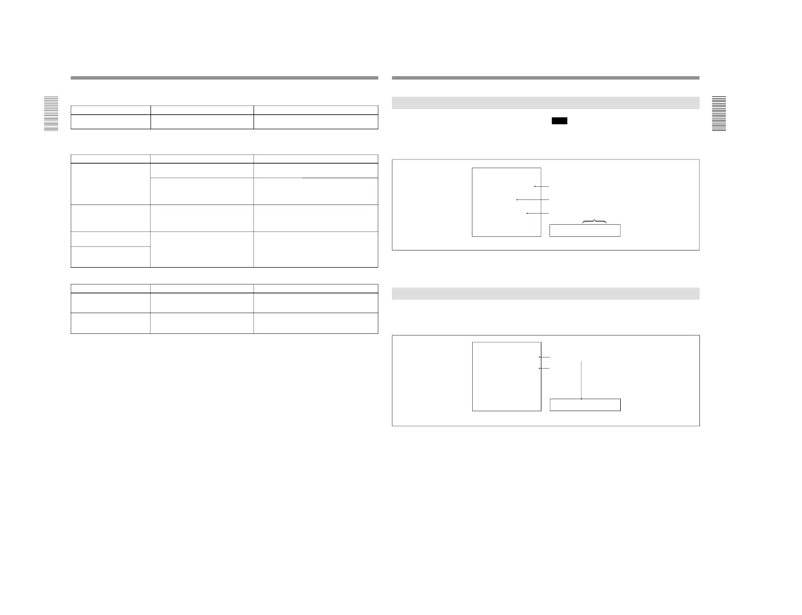
Error Messages
This unit is provided with a self-diagnostic function
that detects internal abnormalities. When it detects an
abnormality, it outputs an error message to the monitor
connected to the unit and indicates an error code in the
display section of the unit.
Note
To display error messages on the monitor screen, set
the CHARACTER switch on the subsidiary control
panel to ON.
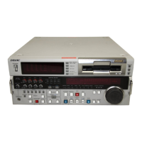
Cause of alarm
Direction
Monitor screen Display section
If an alarm message appears, follow the direction
indicated under the message on the monitor screen.
To display alarm messages on the monitor screen, set
the CHARACTER switch on the subsidiary control
panel to ON, and setup menu item 016 (ALARM) to
ON or LIMIT.
For details of setup menu operations, see Chapter 6
“Setup
Menu” (page 107).
If an error message appears, follow the direction
indicated under the message on the monitor screen.
Alarm Messages