39
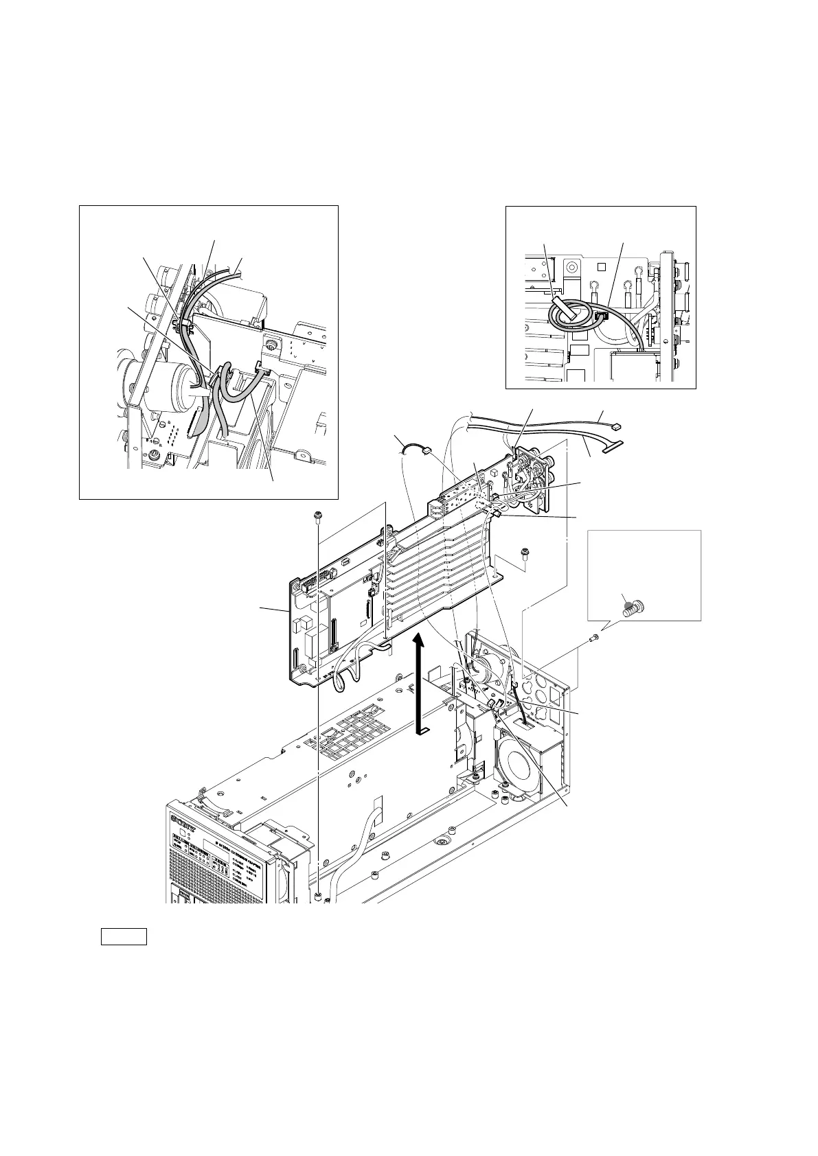
2. Release the harness (a) from the cable clamp (a), and then disconnect the harness (a) from the connector (CN303) on the VIF-82
board.
3. Release the harness (b) from the cable clamp (b), and then disconnect the harness (b) from the connector (CN302) on the VIF-82
board.
4. Release the harness (c) and the fine-wire coaxial cable from the locking edge saddle.
5. Remove the three screws (PSW3 x 8) and the two screws (P2.6 x 5), and then remove the VIF-82 board assembly in the
direction of the arrow.
Note
• At the time of the installation, apply locking compound to the screw (P2.6 x 5) as shown in the figure.
• At the time of the installation, tighten the screws in the following sequence: (a), (b), (c), (d).
• When attaching the VIF-82 board assembly, arrange the three harnesses and the fine-wire coaxial cable as shown in the
figure.
6. Install the removed parts by reversing the steps of removal.
Locking compound 1401B
(Size of a grain of rice)
Locking compound
application area
VIF-82 board assembly
Arrangement of the harness
Arrangement of the cables
Cable clamps (a)
Harness (a)
Cable clamps (b)
Fine-wire coaxial cable
Harness (c)
Fine-wire coaxial cable
Cable clamp (a)
PSW
3 x 8
PSW
3 x 8
P2.6 x 5
(b)
(d)
(c)
(a)
CN303
CN302
Harness (a)
Harness (c)
Harness (b)
Harness (b)
Locking edge saddle
Locking edge
saddle
Cable
clamp (b)