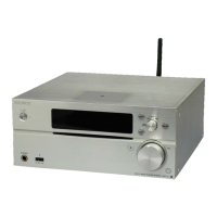
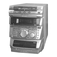
EasyManuals Logo

Sony MAP-S1 Service Manual

Sony MAP-S1
116 pages
To Next Page IconTo Next Page
To Previous Page IconTo Previous Page
Page #25 background imageLoading...
Page #25 background image
MAP-S1
25
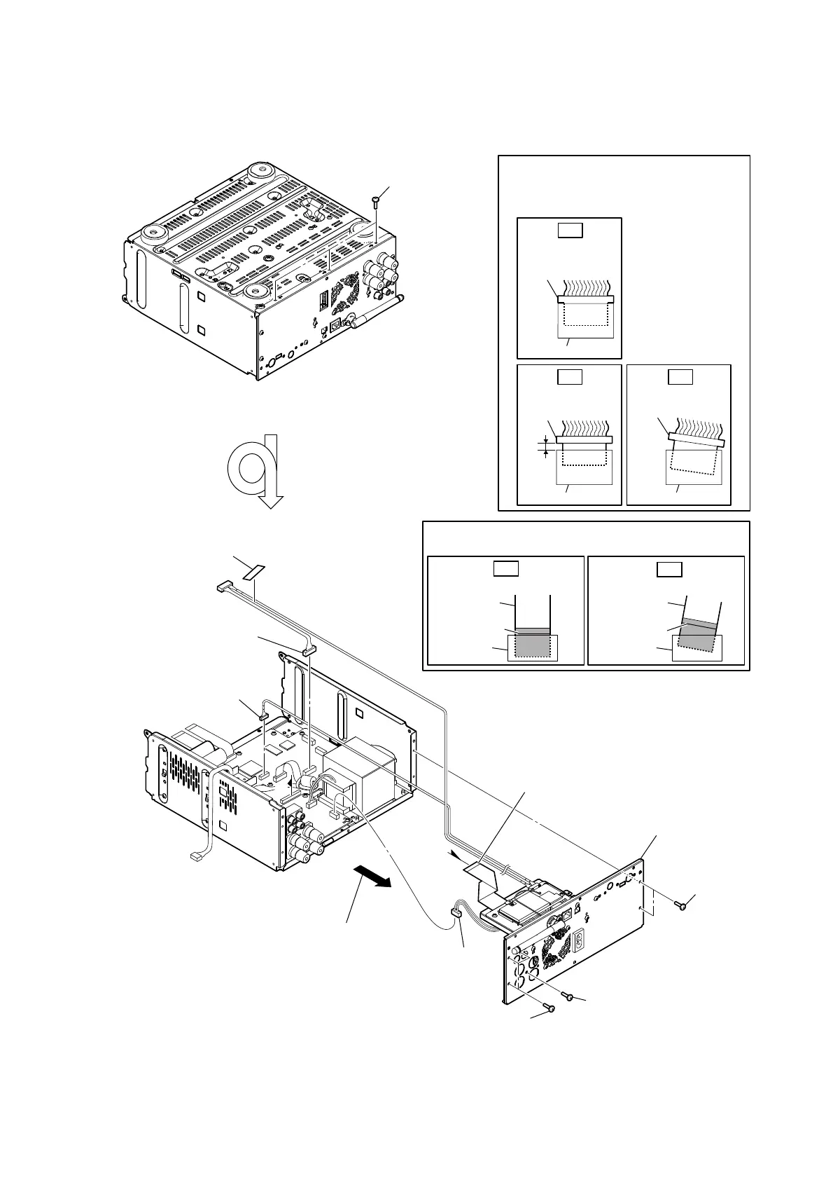
2-19. PANEL BACK BLOCK
A
1 three screws
(BV3)
7 two screws
(BV/ring)
7 three screws
(BV/ring)
– Rear bottom view –
– Rear view –
6 screw
(BV3 u 10 ring)
0 panel back block
4 connector
(CN007)
9 connector
(CN5002)
2 filament tape
(sub material)
3 connector
(CN701)
Insert only part way.
Insert straight into
the interior.
connector
Insert at a slant.
connector
connector
connector
connector connector
OK
NG NG
Note 1:
Insert the connector straight into the interior.
There is a possibility that using this device
without the connector correctly installed will
damage it.
colored line
Insert straight into the interior.
flexible flat
cable
connector
OK
colored line
Insert at a slant.
flexible flat
cable
connector
NG
Note 2:
When installing the flexible flat cable, ensure that
the colored line is parallel to the connector after insertion.
5 flexible flat cable (31P)
(CN003)
A
8 Remove the panel back block
in the direction of the arrow.

Table of Contents

Other manuals for Sony MAP-S1

Questions and Answers:

Question and Answer IconNeed help?

Do you have a question about the Sony MAP-S1 and is the answer not in the manual?

Sony MAP-S1 Specifications

General IconGeneral
Receiver typestereo
Audio output channels2.0 channels
Power output per channel (20-20KHz@8 Ohm)100 W
HDMI in0
Audio (L/R) in1
Connectivity technologyWired & Wireless
Speakers connectivity typeBinding post
Ethernet LANYes
Supported radio bandsAM, FM
Optical drive typeCD player
Card reader integratedNo
Display-
Product colorSilver
Volume controlRotary
Apple docking compatibilityNot supported
Power consumption (standby)0.4 W
Power consumption (typical)55 W

Related product manuals