MAP-S1
38
SECTION 4
ELECTRICAL CHECKS
TUNER SECTION
0 dB = 1 V
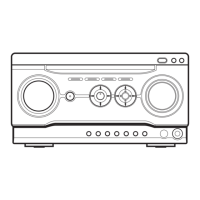
FM TUNE LEVEL CHECK
signal
generator
unit
Procedure:
1. Press the [
?
/
1
] button to turn the power on.
2. Input the following signal from signal generator to FM antenna
input directly.
Carrier frequency : A = 87.5 MHz, B = 98 MHz, C = 108 MHz
Deviation : 75 kHz
Modulation : 1 kHz
ANT input : 35 dBu (EMF)
Note: Use 75 ohm coaxial cable to connect signal generator and the unit.
You cannot use video cable for checking.
Use signal generator whose output impedance is 75 ohm.
3. Press the [FUNCTION] button on the remote commander to
select the FM tuner function and tune A, B and C signals.
4. Confi rm “TUNED” is lit on the display for A, B and C signals.
When the selected station signal is received in good condition,
“TUNED” is displayed.
CD SECTION
Note:
1. CD block is basically constructed to operate without adjustment.
2. Use HLX-A1 disc (Part No. J-2501-307-A) unless otherwise indicat-
ed.
3. Clean the object lens by an applicator with neutral detergent when the
check result is “NG” with the following check.
SERVO CHECK
It can confi rm the servo function.
Note 1: A button having no particular description in the text, indicates the
main unit button.
Also the remote commander use the following.
Part No. Description
1-489-989-11 REMOTE COMMANDER (RM-AMU139)
Procedure:
1. Press the [
?
/
1
] button to turn the power on.
2. Press the [FUNCTION] button on the remote commander to
select the CD function.
3. Press two buttons of the [
u
] and [PUSH ENTER] simultane-
ously for fi ve seconds, or press the buttons on the remote com-
mander in order of the [ALPHABET SEARCH] → [9] → [1]
→ [ENTER] (press the next button within three seconds).
Note 2: The specifi cations are the same even if entering to the check mode
by either operation.
4. Check that “SET DISC” is displayed on the fl uorescent indica-
tor tube.
Screen display
SET DISC
5. Insert the disc (HLX-A1) in the unit.
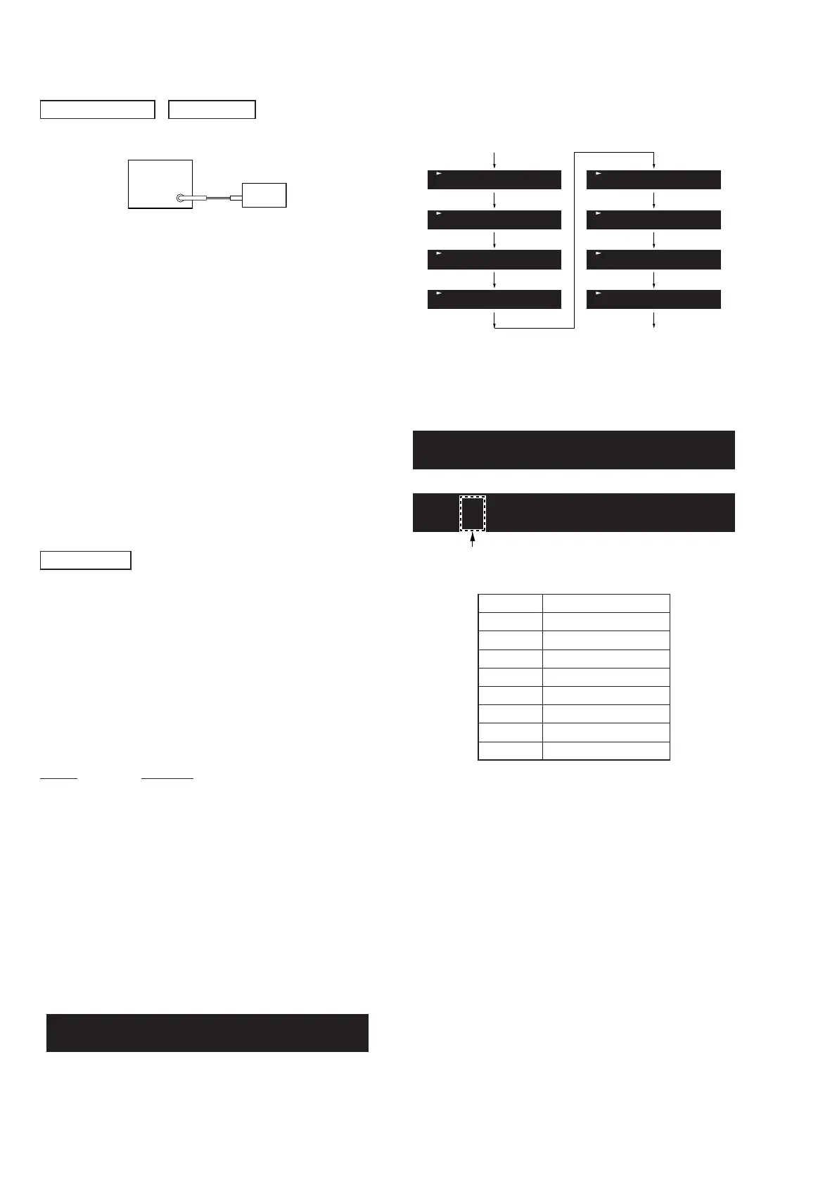
6. Servo check is started, following screen is displayed on the
fl uorescent indicator tube.
Servo check start
Servo check end
T-1
T-2
T-3
T-4
T-5
T-6
T-7
T-8
7. When servo check is ended, the disc (HLX-A1) is ejected au-
tomatically, and “PASS” or “NG X” (X: error No. (1 to 8)) is
displayed on the fl uorescent indicator tube.
Screen display
PASS
NG X
or
Error No.
(1 to 8)
Error No.
Servo Check Item
1 Disc Type
2 SPFG (No Check)
3 Mirror Time
4 TE_Level
5 S_Level
6 S_Balance
7 RFLvl
8 Jitter
Releasing method:
• Press two buttons of the [
u
] and [PUSH ENTER] simultane-
ously for fi ve seconds.
• Press the buttons on the remote commander in order of the
[ALPHABET SEARCH] → [9] → [1] → [ENTER].
(Press the next button within three seconds)
• Press the [FUNCTION] button on the remote commander to
select the except CD function.
• Press the [
?
/
1
] button to turn the power off.