MAP-S1
27
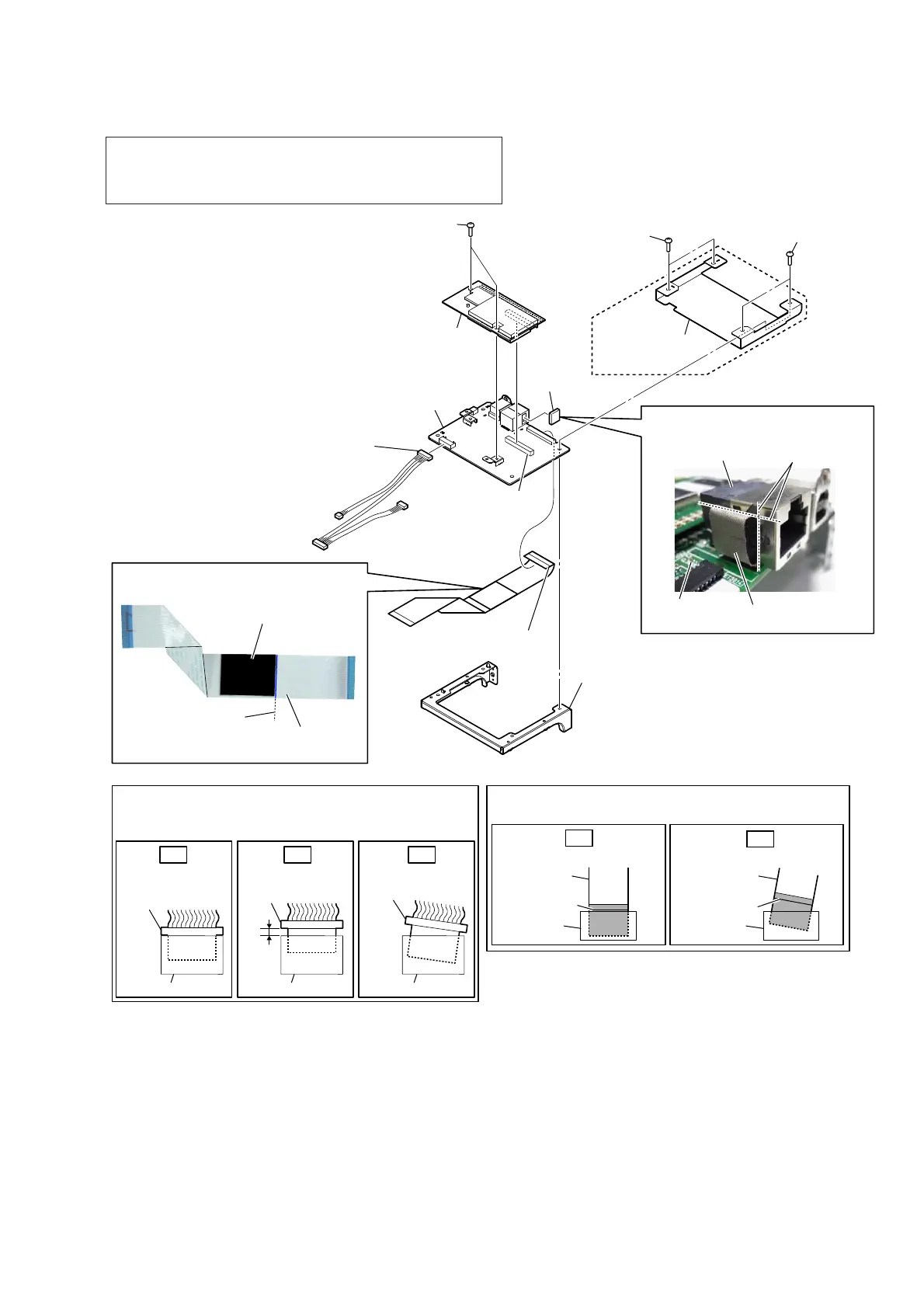
2-22. WiFi MODULE (WIFI1), NETWORK BOARD
+RZWRLQVWDOOWKHJDVNHW/$1
+RZWRLQVWDOOWKHFXVKLRQ32:(5%
2 two screws
(BV3)
1 connector
(CN3009)
3 connector
(CN3001)
0 NETWORK
board
NETWORK
board
9 gasket
(LAN)
4 WiFi module
(WIFI1)
7 braket
PWB NET
cushion
(POWER B)
gasket (LAN)
J3001
8 flexible flat cable (31P)
(CN3010)
guide line
flexible flat cable
(31P)
guide line
Note 2:
Insert the connector straight into the interior.
There is a possibility that using this device without
the connector correctly installed will damage it.
Insert only part way.
Insert straight into
the interior.
connector
Insert at a slant.
connector
connector
connector
connector connector
2. 1* 1*
colored line
Insert straight into the interior.
flexible flat
cable
connector
2.
colored line
Insert at a slant.
flexible flat
cable
connector
1*
Note 3:
When installing the flexible flat cable, ensure that
the colored line is parallel to the connector after insertion.
5 two screws
(BV/ring)
5 two screws
(BVTP3 u 8)
6 cover
(PWB NET)
&DQDGLDQ
Note 1: When the WiFi module (Ref. No. WIFI1) is replaced, refer to
“NOTE OF REPLACING THE WiFi MODULE”, “PROCESS-
ING OF REPLACING THE WiFi MODULE” and “CHECKING
METHOD OF NETWORK CONNECTION” on page 6.