EasyManua.ls Logo

Sony MAP-S1 - Service Manual

Sony MAP-S1
116 pages
Print Icon
To Next Page IconTo Next Page
Loading...
SERVICE MANUAL
Sony Corporation
Published by Sony Techno Create Corporation
SPECIFICATIONS
MULTI AUDIO PLAYER SYSTEM
9-893-994-01
2014C33-1
©
2014.03
Canadian Model
AEP Model
UK Model
Australian Model
Hong Kong Model
Malaysia Model
Ver. 1.0 2014.03
Model Name Using Similar Mechanism NEW
CD Mechanism Type CDM91A-DVBU203
Optical Pick-up Block Name CMS-S76RFS7G
Note:
Be sure to keep your PC used for service and
checking of this unit always updated with the
latest version of your anti-virus software.
In case a virus affected unit was found during
service, contact your Service Headquarters.
– Continued on next page –
MAP-S1
Amplier section
Power output (rated):
50 watts + 50 watts (at 4 ohms, 1 kHz)*
1
*
1
Measured under the following conditions:
Power requirements: 230V AC, 50Hz
(Except Canadian model)
Inputs/Outputs
LINE IN (external input) jack:
Sensitivity: 2 V
Impedance: 47 kilo ohms
LINE OUT (external output) jack:
Output voltage: 2 V
Impedance: 1 kilo ohms
5 Hz – 80 kHz (-3 dB)
PHONES (headphone) jack:
Stereo standard jack, 8 ohms or more
USB:
USB port: Type A, 5 V DC 2.1 A
DIGITAL IN jack:
USB port: Type B
CD-DA/MP3 player section
System:
Compact disc and digital audio system
Laser Diode Properties:
Emission Duration: Continuous
Laser Output*
2
: Less than 44.6 μW
*
2
This output is the value measurement at a
distance of 200mm from the objective lens
surface on the Optical Pick-up Block with 7mm
aperture.
Frequency response:
10 Hz – 20 kHz
Signal-to-noise ratio:
More than 90 dB
Dynamic range:
More than 90 dB
Tuner section
AM tuner section:
Tuning range:
AEP, UK, Hong Kong and Malaysia models:
531 kHz-1,602 kHz (with 9 kHz tuning
interval)
Other models:
530 kHz-1,710 kHz (with 10 kHz tuning
interval)
531 kHz-1,710 kHz (with 9 kHz tuning
interval)
Antenna:
AM loop antenna
Intermediate frequency:
400 kHz
FM tuner section:
FM stereo, FM superheterodyne tuner
Tuning range:
87.5 MHz – 108.0 MHz (100 kHz step)
(Canadian model)
87.5 MHz – 108.0 MHz (50 kHz step)
(Except Canadian model)
Antenna:
FM lead antenna
Antenna terminals:
DAB/FM lead antenna
75 ohms unbalanced
DAB/DAB+ tuner section:
(Except Canadian model)
FM stereo, DAB/FM superheterodyne tuner
Frequency range:
Band-III:
174.928 (5A) MHz – 239.200 (13F) MHz*
3
Antenna:
DAB/FM lead antenna:
DAB/DAB+ frequency table (Band-III):
Frequency Label
174.928 MHz 5A
176.640 MHz 5B
178.352 MHz 5C
180.064 MHz 5D
181.936 MHz 6A
183.648 MHz 6B
185.360 MHz 6C
187.072 MHz 6D
*
3
Frequencies are displayed to two decimal places
on this system.
188.928 MHz 7A
190.640 MHz 7B
192.352 MHz 7C
194.064 MHz 7D
195.936 MHz 8A
197.648 MHz 8B
199.360 MHz 8C
201.072 MHz 8D
202.928 MHz 9A
204.640 MHz 9B
206.352 MHz 9C
208.064 MHz 9D
209.936 MHz 10A
211.648 MHz 10B
213.360 MHz 10C
215.072 MHz 10D
216.928 MHz 11A
218.640 MHz 11B
220.352 MHz 11C
222.064 MHz 11D
223.936 MHz 12A
225.648 MHz 12B
227.360 MHz 12C
229.072 MHz 12D
230.784 MHz 13A
232.496 MHz 13B
234.208 MHz 13C
235.776 MHz 13D
237.488 MHz 13E
Frequency Label
239.200 MHz 13F

Table of Contents

Other manuals for Sony MAP-S1

Question and Answer IconNeed help?

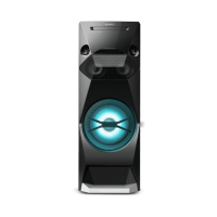
Do you have a question about the Sony MAP-S1 and is the answer not in the manual?

Summary

Product Specifications

Amplifier, CD, and Tuner Specifications

Details on amplifier power, CD/MP3 player capabilities, and AM/FM/DAB tuner ranges.

Connectivity and Safety

Bluetooth, Wireless LAN, and General Specs

Bluetooth, Wi-Fi standards, power requirements, dimensions, and mass.

Safety Check-out and Leakage Testing

Crucial post-repair safety checks, including AC leakage testing methods.

Servicing Notes and Procedures

Disassembly, Test Modes, and Electrical Checks

Guides for unit disassembly, test modes, and electrical checks.

Diagrams, Views, and Parts Lists

References to system diagrams, exploded views, and the electrical parts list for servicing.

Specific Component Handling and Replacement

Optical Pick-up, Laser Diode, and Board Replacement Notes

Precautions for optical pick-up, laser diode, and guidance on replacing specific boards and ICs.

Board Version Identification

Guidance on distinguishing board versions for Canadian models.

Service Aids and Identification

Test Discs, Capacitor Safety, and Model ID

Information on test discs, capacitor discharge, and unit model identification.

Network Module and User Data Service

WiFi Module Replacement and Network Connection Checks

Procedures for replacing the WiFi module and checking network connectivity.

User Registration Reset

Method for deleting user registration of SEN service by checking Device ID.

CD Mechanism Service Procedures

Ejecting Disc and Service Position

Instructions for disc ejection with power off and the unit's service position diagram.

Unit Panel Disassembly

Side and Front Panel Removal

Detailed steps for removing the side panels and the first block of the front panel.

Front Panel Disassembly - Block 2

Removing Front Panel Block-2 and Cables

Instructions for removing the second front panel block and notes on cable insertion.

Component Block Disassembly

Bracket Jack Block and Front Boards

Disassembly steps for the bracket jack block and front-R/front-key boards.

Front Section Board Disassembly

Front-Eject, Front-L, and Front Boards

Procedures for removing front-section boards and notes on flat cable installation.

Bluetooth NFC Holder Service

NFC Holder Block Disassembly and Cable Notes

Steps for removing the NFC holder block and notes on flexible flat cable handling.

CD Mechanism Deck Block Service

CD Mechanism Deck Block Removal and Installation Notes

Instructions for removing the CD mechanism deck block and notes on connector/cable insertion.

CD Mechanism Components Service

CD Mechanism Deck and FFC Guide Disassembly

Steps for disassembling the CD mechanism deck and removing the FFC guide.

Bottom Cover Service

Bottom Cover (I) Removal Procedure

Detailed steps for removing the bottom cover (Part I) of the CD mechanism deck.

Optical Pick-up Block Service

Optical Pick-up Block Removal and Installation Precautions

Steps for handling the optical pick-up block, including connector and cable installation.

Tuner Board Block Service

Tuner Board Block Removal and Flat Cable Notes

Instructions for removing the tuner board block and notes on flexible flat cable installation.

Tuner Board Service

Tuner Board Component Handling and Reassembly

Servicing the tuner board, including flexible flat cable and ferrite core reassembly.

DAB Board Service

DAB Board Block and Module Removal Procedures

Procedures for removing DAB boards and modules, with flat cable installation notes.

Panel Back Block Service

Panel Back Block Removal and Connection Notes

Steps for removing the panel back block and guidelines for connector/cable insertion.

Antenna and Network Board Service

Antenna Holder and Network Board Block Removal

Instructions for antenna holder replacement and network board block removal.

Network Connection Verification Reference

Reference to checking network connection methods after WiFi antenna replacement.

WiFi Module and Network Board Service

WiFi Module and Network Board Replacement Steps

Procedures for replacing WiFi module and network board, with connector and cable notes.

AC Inlet Service

AC Inlet Replacement Procedure

Steps for replacing the AC inlet, including binding band handling for reassembly.

Amplifier Board Block Service

AMP Board Block Removal and Installation Guidelines

Instructions for removing and installing the amplifier board block, including claw fitting and cable notes.

Amplifier Board Service

Amplifier Board Component Handling and Flat Cable Notes

Detailed steps for servicing the amplifier board, including binding band cutting and flat cable installation.

Main Board Service

Main Board Removal and Wire Setting Guidance

Instructions for removing the main board and notes on proper wire routing.

Power Supply and Main Transformer Service

Power Board and Main Transformer Replacement

Steps for replacing power board and main transformer, including wire setting.

Test Mode Operations

RF Mode and Unit Reset Procedures

Procedures for RF mode control and clearing unit memory (reset).

Common Test and Volume Adjustment

Steps for confirming sound functions and adjusting volume settings in test mode.

Panel Test and Version Display

Panel Test Procedures and Display Information

Steps for testing panel elements and displaying unit version information.

Advanced Test Modes

Version Information and WiFi Reception Level

Procedures for checking software version and WiFi signal reception level.

Auto Standby Test

Auto Standby Function Test Procedure

Steps to confirm the operation of the auto standby function and its countdown timer.

Electrical Checks

FM Tune Level and CD Servo Checks

Procedures for checking FM tuning level and CD servo function, including test disc usage.

System Block Diagrams

CD;USB Section Block Diagram

Block diagram detailing the CD and USB signal paths and component interconnections.

Audio System Block Diagrams

Audio Section Block Diagram

Block diagram illustrating the audio signal flow from various sources to the output stages.

Amplifier System Block Diagrams

Amplifier Section Block Diagram

Block diagram showing the amplifier signal paths, including DACs and output stages.

Power and Control System Diagrams

Panel and Power Supply Block Diagram

Block diagram of the panel control, power supply circuits, and regulators.

Diagram Interpretation and Reference

Circuit Board Locations, Abbreviations, and Notes

Guidance on interpreting diagrams, locating boards, and understanding abbreviations.

Printed Wiring Boards - Main Section (Suffix-11)

Main Board (1;2) Component Layout (Canadian)

Component layout for the Main board (1/2) for Canadian models (Suffix-11).

Printed Wiring Boards - Main Section (Suffix-11)

Main Board (2;2) Component Layout (Canadian)

Component layout for the Main board (2/2) for Canadian models (Suffix-11).

Printed Wiring Boards - Main Section (Suffix-12)

Main Board (1;2) Component Layout (Suffix-12)

Component layout for the Main board (1/2) for models with Suffix-12.

Printed Wiring Boards - Main Section (Suffix-12)

Main Board (2;2) Component Layout (Suffix-12)

Component layout for the Main board (2/2) for models with Suffix-12.

Schematic Diagrams - Main Section (1;7)

Main Board Schematic - Section 1

Schematic diagram for the Main board, section 1 of 7, showing ICs and connections.

Schematic Diagrams - Main Section (2;7)

Main Board Schematic - Section 2

Schematic diagram for the Main board, section 2 of 7, detailing IC pinouts and connections.

Schematic Diagrams - Main Section (3;7)

Main Board Schematic - Section 3

Schematic diagram for the Main board, section 3 of 7, showing connections to other boards.

Schematic Diagrams - Main Section (4;7)

Main Board Schematic - Section 4

Schematic diagram for the Main board, section 4 of 7, illustrating IC functions and pin assignments.

Schematic Diagrams - Main Section (5;7)

Main Board Schematic - Section 5

Schematic diagram for the Main board, section 5 of 7, including waveform examples and logic circuits.

Schematic Diagrams - Main Section (6;7)

Main Board Schematic - Section 6

Schematic diagram for the Main board, section 6 of 7, showing board interconnections and signal paths.

Schematic Diagrams - Main Section (7;7)

Main Board Schematic - Section 7

Schematic diagram for the Main board, section 7 of 7, focusing on power supply and regulator circuits.

Network Board Schematic Diagrams

Network Board Schematic Diagram

Schematic diagram of the network board, showing ICs, connectors, and their interconnections.

Network Board Wiring - Suffix-11

Network Board Component Layout (Canadian)

Printed wiring board layout for the network board (component/conductor sides) for Canadian models.

Network Board Wiring - Suffix-12

Network Board Component Layout (Suffix-12)

Printed wiring board layout for the network board (component/conductor sides) for models with Suffix-12.

USB and Headphone Board Layouts

USB;HP Boards Wiring Diagrams

Printed wiring board layouts for the USB and Headphone boards, detailing component placement.

USB and Headphone Board Schematics

USB;HP Boards Schematic Diagram

Schematic diagram for the USB and Headphone boards, showing ICs and connections.

Front-L Board Wiring - Suffix-11

Front-L Board Component Layout (Canadian)

Printed wiring board layout for the Front-L board (component/conductor sides) for Canadian models.

Front-L Board Wiring - Suffix-12

Front-L Board Component Layout (Suffix-12)

Printed wiring board layout for the Front-L board (component/conductor sides) for models with Suffix-12.

Front-L Board Schematic Diagram

Front-L Board Schematic

Schematic diagram for the Front-L board, detailing ICs and connections.

Amplifier Board Schematic Diagrams

Amplifier Board Schematic

Schematic diagram of the amplifier board, showing ICs, transistors, and their interconnections.

Amplifier Board Wiring (Component Side) - Suffix-11

AMP Board Component Layout (Canadian)

Component layout for the amplifier board (component side) for Canadian models.

Amplifier Board Wiring (Conductor Side) - Suffix-11

AMP Board Conductor Layout (Canadian)

Component layout for the amplifier board (conductor side) for Canadian models.

Amplifier Board Wiring (Component Side) - Suffix-12

AMP Board Component Layout (Suffix-12)

Component layout for the amplifier board (component side) for models with Suffix-12.

Amplifier Board Wiring (Conductor Side) - Suffix-12

AMP Board Conductor Layout (Suffix-12)

Component layout for the amplifier board (conductor side) for models with Suffix-12.

Front Board Wiring Layout

Front Board Component Layout

Printed wiring board layout for the front board, showing component placement.

Front Board Schematic Diagram

Front Board Schematic

Schematic diagram for the front board, illustrating connections to the fluorescent indicator tube.

Key Section Schematic Diagrams

Front-R, Front-Key, Front-Eject Board Schematics

Schematic diagrams for front-R, front-key, and front-eject boards detailing button and encoder connections.

Key Section Wiring Layouts

Front Board Key Component Layouts

Printed wiring board layouts for front-R, front-key, and front-eject boards showing component placement.

Subpower Board Wiring Layout

Subpower Board Component Layout

Printed wiring board layout for the subpower board, showing component placement and transformer connections.

Subpower Board Schematic Diagram

Subpower Board Schematic

Schematic diagram for the subpower board, illustrating power supply circuits and component connections.

Signal Waveforms

Main and Front Board Waveforms

Examples of oscilloscope waveforms for ICs on the main and front boards.

Integrated Circuit Block Diagrams

Main Board IC Block Diagrams

Block diagrams illustrating the internal functions of key ICs on the main board.

Power Management IC Block Diagrams

DC;DC Converter and Regulator IC Block Diagrams

Block diagrams for power management ICs like TPS54332CDDAR and MM3374A33PRE.

Logic Gate and Multiplexer IC Block Diagrams

TC74 VHC Logic IC Block Diagrams

Block diagrams for TC74VHC series logic gate and multiplexer ICs.

Audio Processing IC Block Diagrams

Audio ADC and DAC IC Block Diagrams

Block diagrams for audio Analog-to-Digital and Digital-to-Analog converter ICs.

Audio Signal Control IC Block Diagrams

Audio DAC and Signal Selector IC Block Diagrams

Block diagrams for audio DACs, signal selectors, and clock managers.

Interface IC Block Diagrams

USB and Network Interface IC Block Diagrams

Block diagrams for USB power switch, network ICs, and interface controllers.

Amplifier IC Block Diagrams

Amplifier ICs and Control Logic Block Diagrams

Block diagrams for amplifier ICs, detailing control and protection features.

IC Pin Function Descriptions

Main Board IC203 Pinout Description

Detailed pin descriptions for IC203 (Audio DSP, System Controller).

IC Pin Function Descriptions Continued

Main Board IC Pinout Details (Pins 56-114)

Continuation of pin descriptions for main board ICs, covering pins 56 through 114.

IC Pin Function Descriptions Continued

Main Board IC Pinout Details (Pins 115-176)

Continuation of pin descriptions for main board ICs, covering pins 115 through 176.

IC Pin Function Descriptions Continued

Main Board IC503 Pinout Description

Detailed pin descriptions for IC503 (RF Amplifier, Servo/Audio Processor).

IC Pin Function Descriptions Continued

Main Board IC503 Pinout Details (Pins 1-79)

Continuation of pin descriptions for IC503, covering pins 1 through 79.

IC Pin Function Descriptions Continued

Main Board IC503 Pinout Details (Pins 80-128)

Continuation of pin descriptions for IC503, covering pins 80 through 128.

Exploded Views

Panel (Side) Section Exploded View

Exploded view of the unit's side panels and associated hardware with part numbers.

Bracket CDM Section Exploded View

CD Mechanism Bracket Assembly Exploded View

Exploded view of the CD mechanism bracket, showing screws, clamps, and FFC connectors.

Front-L Board Section Exploded View

Front Panel Components Assembly Exploded View

Exploded view of the front panel assembly, detailing buttons, knobs, and associated boards.

Front Panel Assembly Exploded View

Front Panel Components and Module Exploded View

Exploded view of the front panel, showing indicator, buttons, NFC module, and Bluetooth module.

CD Mechanism Deck Exploded View

CD Mechanism Deck Assembly Exploded View

Exploded view of the CD mechanism deck, including FFC guide and loading Assy.

Optical Pick-up Section Exploded View

Optical Pick-up Block Assembly Exploded View

Exploded view of the optical pick-up block, showing insulators, FFC, and the block itself.

Amplifier Board Section Exploded View

Amplifier Board Assembly Exploded View

Exploded view of the amplifier board assembly, showing screws, FFC, and ferrite core clamp.

Tuner Section Exploded View

Tuner and DAB Board Assembly Exploded View

Exploded view of the tuner and DAB board assembly, including connectors and screws.

Back Panel Section Exploded View

Back Panel Components Assembly Exploded View

Exploded view of the back panel, showing network board, WiFi module, antenna, and fan.

Chassis Section Exploded View

Chassis Assembly with Boards and Transformer Exploded View

Exploded view of the chassis, showing main board, subpower board, transformer, and hardware.

Electrical Parts List

Component Details and Specifications

Comprehensive list of electrical components with part numbers, descriptions, and specifications.

Electrical Parts List Continued

Resistors, Transistors, and Connectors

List of resistors, transistors, connectors, and other components with their part numbers.

Electrical Parts List Continued

Resistors, Diodes, Fuses, and ICs

List of resistors, diodes, fuses, ICs, and their specifications.

Electrical Parts List Continued

Transistors, Switches, and Front Board Components

List of transistors, switches, and components for the front boards.

Electrical Parts List Continued

Front-L, Front-R, HP, and Main Board Components

List of components for Front-L, Front-R, HP, and Main boards.

Electrical Parts List Continued

Capacitors and Connectors

List of various capacitors and connectors with their part numbers and specifications.

Electrical Parts List Continued

Capacitors and Resistors

List of capacitors and resistors with detailed specifications and part numbers.

Electrical Parts List Continued

Connectors, Diodes, Fuses, and ICs

List of connectors, diodes, fuses, and ICs with part numbers and associated notes.

Electrical Parts List Continued

Resistors and Transistors

List of resistors and transistors with part numbers, specifications, and remarks.

Electrical Parts List Continued

Resistors

Continuation of the resistor list with detailed part numbers and specifications.

Electrical Parts List Continued

Resistors

Continuation of the resistor list with detailed part numbers and specifications.

Electrical Parts List Continued

Resistors

Continuation of the resistor list with detailed part numbers and specifications.

Electrical Parts List Continued

Resistors

Continuation of the resistor list with detailed part numbers and specifications.

Electrical Parts List Continued

Resistors, Connectors, ICs, and Miscellaneous

List of resistors, connectors, ICs, and miscellaneous parts with part numbers.

Electrical Parts List Continued

Capacitors, Connectors, Diodes, Fuses, Transistors, and Transformers

List of capacitors, connectors, diodes, fuses, transistors, and transformers.

Electrical Parts List Continued

ICs, Resistors, Miscellaneous Parts, and Notes

List of ICs, resistors, miscellaneous items, and important notes regarding replacements.

Accessories

Manuals, Setup Guides, and Included Accessories

List of instruction manuals, quick setup guides, remote commander, antennas, power cord, and other accessories.

Revision History

Manual Revision Log

Record of revisions made to the manual, including version number and date.

Sony MAP-S1 Specifications

General IconGeneral
Receiver typestereo
Audio output channels2.0 channels
Power output per channel (20-20KHz@8 Ohm)100 W
HDMI in0
Audio (L/R) in1
Connectivity technologyWired & Wireless
Speakers connectivity typeBinding post
Ethernet LANYes
Supported radio bandsAM, FM
Optical drive typeCD player
Card reader integratedNo
Display-
Product colorSilver
Volume controlRotary
Apple docking compatibilityNot supported
Power consumption (standby)0.4 W
Power consumption (typical)55 W

Related product manuals