EasyManuals Logo

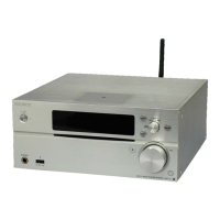
Sony MAP-S1 Service Manual

Sony MAP-S1
116 pages
To Next Page IconTo Next Page
To Previous Page IconTo Previous Page
Page #32 background imageLoading...
Page #32 background image
MAP-S1
32
2-27. POWER BOARD
2-28. MAIN TRANS (T1)
A
A
4
screw
(BV3)
5
coating clip
7
clamp filter
(ferrite core)
(FC6)
1
Remove the wires
from the lead pin.
2
connector
(CN5001)
3
connector
(CN5003)
4
three screws
(BV3)
8
POWER board
6 Remove the POWER
board block in the
direction of the arrow.
coating clip
main trans
lead pin
POWER board
:LUHVHWWLQJ
1 filament tape
(sub material)
1 filament tape
(sub material)
3 main trans
(T1)
2 two screws
(BVTT4 u 8)
2 screw
(BVTT4 u 8)
2 screw
(BVTT4 u 8)
:LUHVHWWLQJ
main trans
filament tape
(sub material)
filament tape
(sub material)

Table of Contents

Other manuals for Sony MAP-S1

Questions and Answers:

Question and Answer IconNeed help?

Do you have a question about the Sony MAP-S1 and is the answer not in the manual?

Sony MAP-S1 Specifications

General IconGeneral
Receiver typestereo
Audio output channels2.0 channels
Power output per channel (20-20KHz@8 Ohm)100 W
HDMI in0
Audio (L/R) in1
Connectivity technologyWired & Wireless
Speakers connectivity typeBinding post
Ethernet LANYes
Supported radio bandsAM, FM
Optical drive typeCD player
Card reader integratedNo
Display-
Product colorSilver
Volume controlRotary
Apple docking compatibilityNot supported
Power consumption (standby)0.4 W
Power consumption (typical)55 W

Related product manuals