14
Technical data are subject to change without notice.
ISO 9001 certified. © Copyright SPM 1996-9. 71411.B
SPM Instrument AB • Box 4 • S-645 21 Strängnäs • Sweden
Tel +46 152 22500 • Fax +46 152 15075 • info@spminstrument.se • www.spminstrument.se
Taking Shock Pulse Readings
Pressing any key will start the A2010 in the last used
measuring mode. The SPM/VIB key changes the mode
from vibration to shock pulse monitoring.
The SET key allows to input or change NORM and
TYPE number, to set a COMP number and the number
of measuring cycles to be accumulated. Pressing the
M key will switch from the SET to the measuring
mode.
The user then connects the transducer to the measur-
ing point and presses the M key once. While the
instrument goes through the programmed number of
measuring cycles, the peak indicator blinks and the
bearing data are on the screen. The figure behind Acc
shows the number of completed measuring cycles.
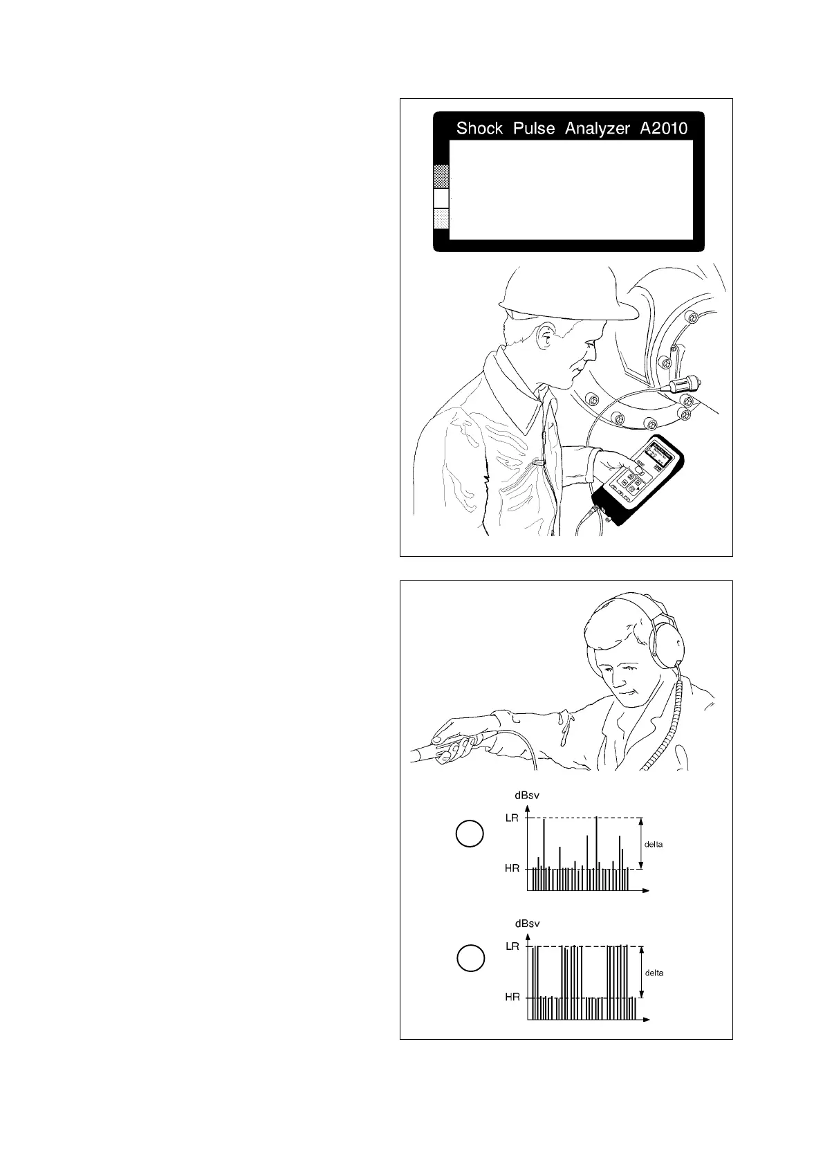
The transducer type used is displayed in the bottom
right hand corner of the screen (fig. 22).
After completing the measurement, the A2010 dis-
plays the bearing’s shock values (LR and HR) together
with CODE, LUB, and COND. An arrow points at the
condition scale, green field for CODE A, yellow for B
and C, red for D.
The Earphone Mode
The earphone mode is a help function for a further
evaluation of shock pulse readings indicating bad bear-
ing condition. It allows the user to listen to the rhythm
of the shock pulses and to determine their probable
origin and cause.
The transducer has to be connected to the measuring
point while the earphones are used. The arrow keys
control the measuring threshold: ”UP” moves it up
the dB
SV
scale, ”DOWN” lowers the threshold. The
peak indicator is active and blinks if there are shock
pulses above the set level.
A machine can contain shock pulse sources other than
the bearings. Mostly, these can be easily identified by
their characteristic sound pattern. Single shock pulses
are heard as single sound pulses, while the shock
pulses at the HR level are heard as a continuous tone.
Figure 23 shows two typical patterns:
A A damaged bearing - strong, irregular, single
peaks well above the HR level
B Scraping or rubbing machine parts - a shower of
peaks at regular intervals.
Fig. 23
A
B
MEASURING . .
NORM 32 Acc 0 / 3
TYPE 1
COMP 0 TRA
Fig. 22