41
Technical data are subject to change without notice.
ISO 9001 certified. © Copyright SPM 1996-9. 71411.B
SPM Instrument AB • Box 4 • S-645 21 Strängnäs • Sweden
Tel +46 152 22500 • Fax +46 152 15075 • info@spminstrument.se • www.spminstrument.se
To assure a correct signal transmission, measuring
points must be selected according to the following
rules:
1 The signal path between bearing and
measuring point shall be as straight and short
as possible.
2 The signal path must contain only one
mechanical interface, that between the
bearing and the bearing housing.
3 The measuring point shall be located within
the load zone of the bearing.
SPM's evaluation rules are not valid if a measuring
point does not conform with these rules. However, a
measuring point that comes at least close to the re-
quirements will yield consistent if somewhat low read-
ings. With LUBMASTER one can calculate a COMP
No. and obtain condition codes even for these bear-
ings. Alternatively one can trend the LR/HR readings.
The signal losses in the two unavoidable interfaces
(bearing – bearing housing and housing – adapter)
have been taken into account in SPM’s evaluation of
bearing condition.
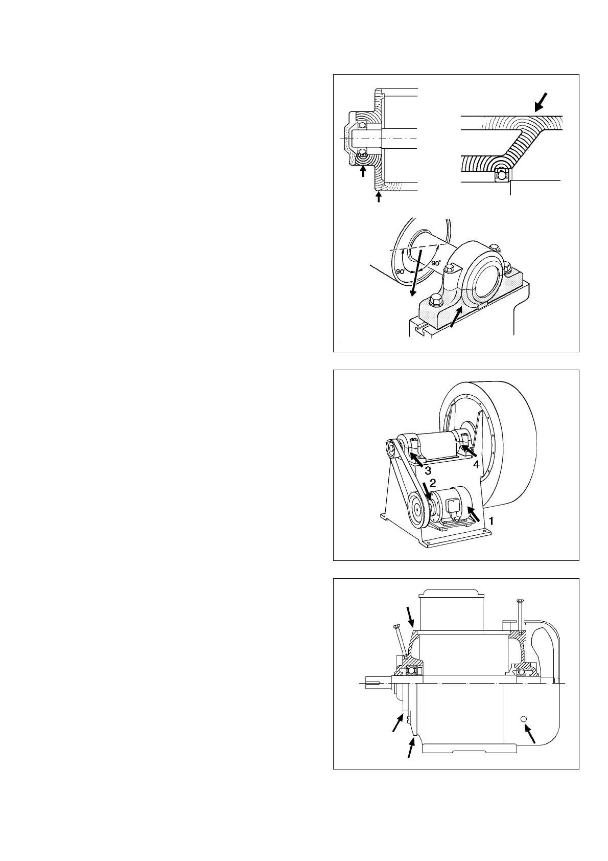
Load Zone
The load zone is defined as the load carrying part of
the bearing housing. It is normally determined by the
weight of the supported machine part, i.e. the load is
mostly on the lower half of the bearing housing.
Consider also the direction of the force acting on the
shaft when the machine is running. Figure 13 shows
how belt tension determines the load on the bear-
ings. The fan shaft in point 3 is pulled down towards
the motor. The drive end of the motor shaft is pulled
up towards the fan (2), the non-drive end is pressed
down and away from the fan. The arrows in figure 13
show the measuring points.
Find the Strongest Signal
Use the probe to find the spot on the bearing housing
where the signal is strongest. If there are several
points yielding the same signal, select the point where
it is easiest to take readings.
Selection of Measuring Points
Fig. 12
Fig. 14
Fig. 13
Load
3
1
2