38
Technical data are subject to change without notice.
ISO 9001 certified. © Copyright SPM 1996-9. 71411.B
SPM Instrument AB • Box 4 • S-645 21 Strängnäs • Sweden
Tel +46 152 22500 • Fax +46 152 15075 • info@spminstrument.se • www.spminstrument.se
Experience Before Full Scale Monitoring
Shock pulse monitoring should be started on a small
scale. The best place to start is a ”quiet corner”
where monitoring personnel can train under good
working conditions, without causing an interruption
or being disturbed by others.
Select a few machines and go through all the opera-
tions listed in figure 5. Keep working with these ma-
chines until you are satisfied with your measuring
routines and can time the various operations, like
adapter installation, taking readings, recording, etc.
Levels of Skill
Shock pulse monitoring requires two levels of skill:
1 data collection
2 machine condition evaluation.
Data collection requires moderate skill: familiarity with
the instrument functions described in part 2 of this
manual, with the follow-up form described in this part,
and some hands-on training with the shock pulse and
vibration transducers. Experience shows that about
nine tenths of the monitoring work is simple data
collection.
Condition evaluation, necessary on new measuring
points and in case of significant changes in the read-
ings, requires additional skills. While the "data collec-
tor" presents instrument readings, the "machine in-
spector" should be able to provide the maintenance
crew with a detailed description of the nature and
location of the trouble spot.
Finding trouble spots is detective work, where the
shock pulse meter is strictly a tool, used with common
sense and backed up by the operator's experience
with the type of equipment that is being monitored.
An important aspect of monitoring work is to con-
vince others that the readings are both useful and
reliable. Measuring personnel with skills at the "ma-
chine inspector" level will find it easier to be believed.
Train all Operations:
1 Selection of measuring points
2 Obtaining basic bearing data
3 Normalized and unnormalized
readings with all transducer types
4 Installation of adapter or stud
5 Preparation of follow-up forms
6 Recording of readings
7 Recognition of typical patterns
(earphone mode)
8 Probing for interference
9 Lubrication test
Fig. 5
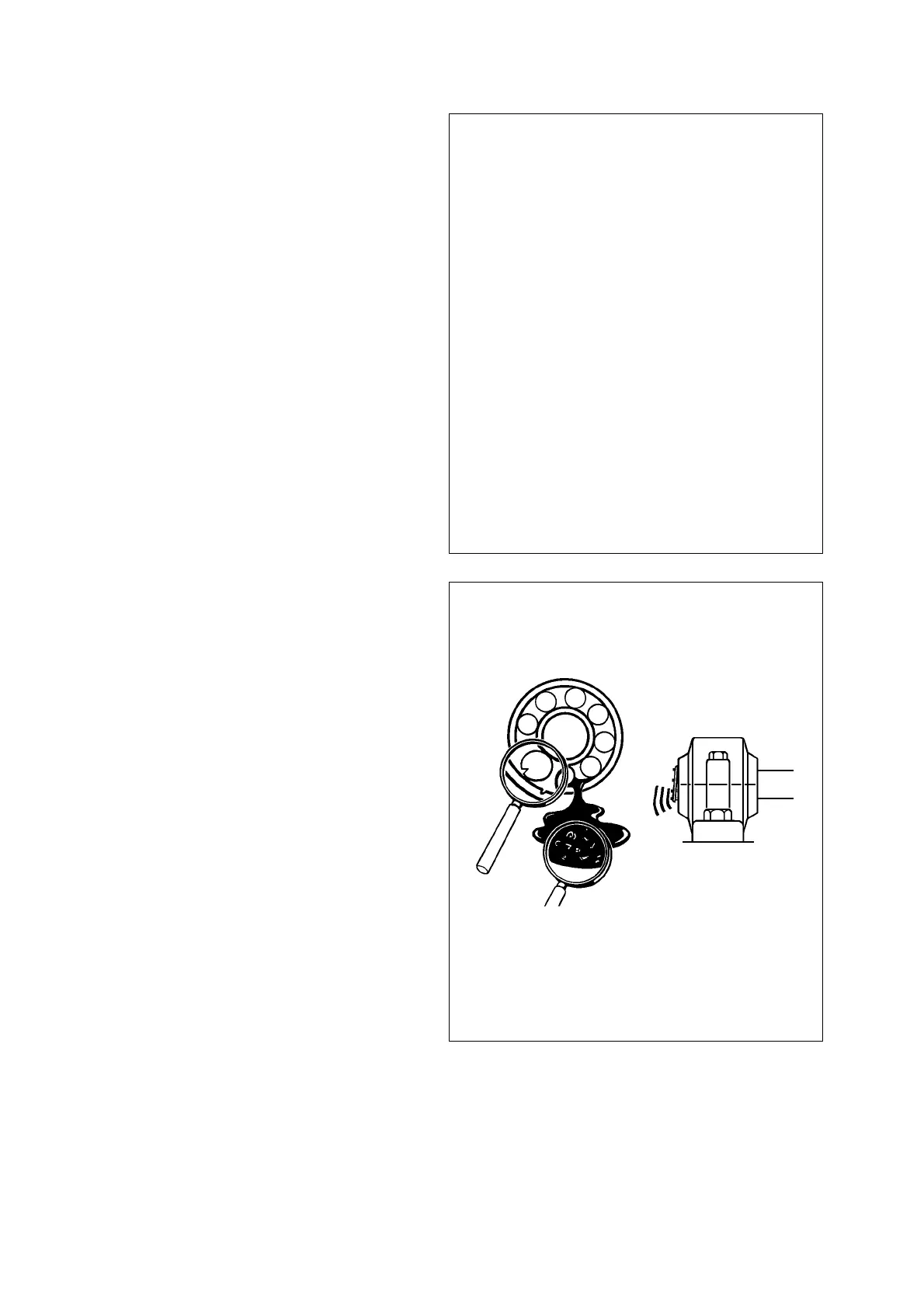
Fig. 6
What causes the
high reading?
The maintenance
crew needs a
correct answer !!