61
Technical data are subject to change without notice.
ISO 9001 certified. © Copyright SPM 1996-9. 71411.B
SPM Instrument AB • Box 4 • S-645 21 Strängnäs • Sweden
Tel +46 152 22500 • Fax +46 152 15075 • info@spminstrument.se • www.spminstrument.se
Vibration at the measuring point should be repre-
sentative of the overall vibration pattern of the ma-
chine. The forces involved are usually transmitted
through the bearings and their housings to the ma-
chine foundation. Consequently, measuring points
should be located on or near the bearing housings.
Machine guards, cover panels and other parts which
are considerably less stiff than the main structure are
not suitable as measuring points.
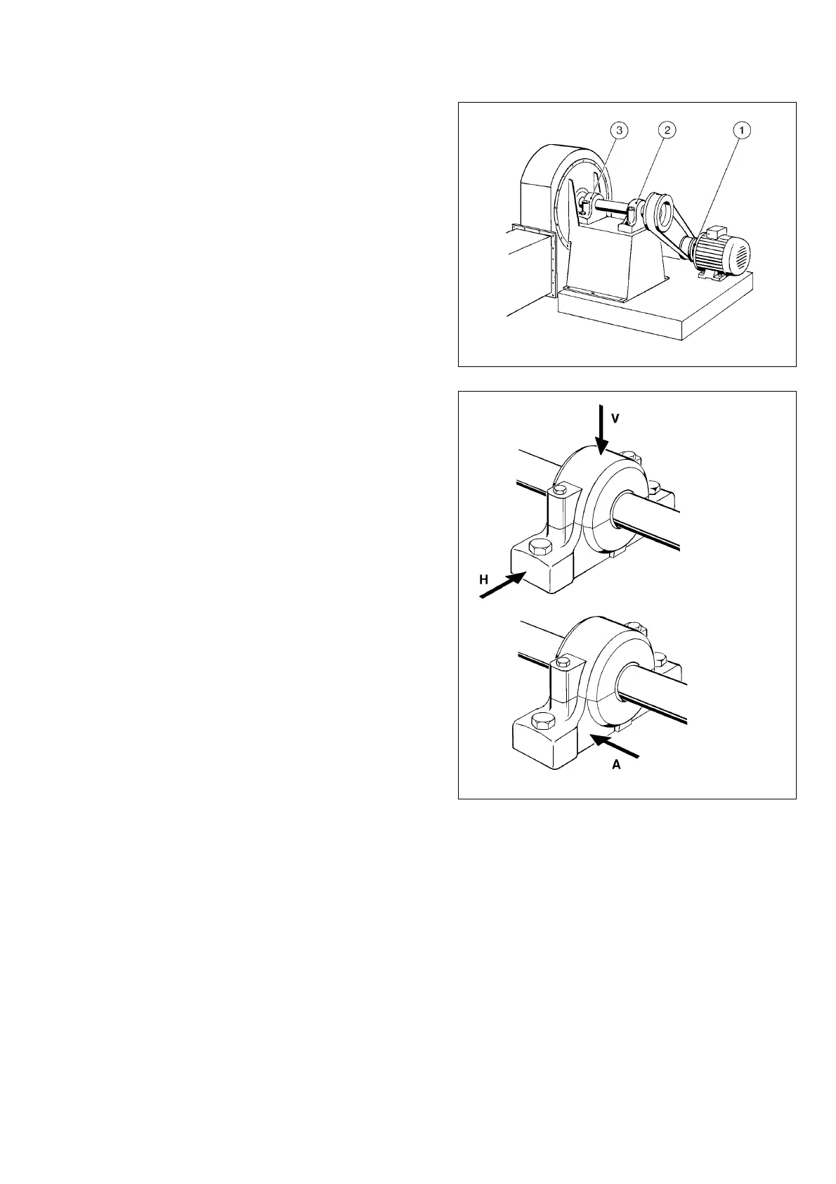
Generally speaking, the more measuring points cho-
sen, the easier it is to locate a specific mechanical
problem. Consider a fan belt driven from an electric
motor. Measurements taken on the fan bearing (3)
will primarily give information on fan balance. If out-
of-balance is the main problem, measuring on that
bearing will be sufficient. To be able to make an
adequate assessment of the mechanical state of the
whole machine, one should also measure on the drive
end bearing (2) and on the motor (1).
Direction of Measurement
Out-of-balance forces rotate with the shaft and cause
radial vibration acting in all directions within the plane
of rotation.
Axial vibration, along with the line of the shaft, is
normally caused by faulty alignment, i.e. badly assem-
bled couplings or bent shafts.
Normal practice is to take readings in three directions
at each measuring point: vertical (V), horizontal (H)
and axial (A). Of the two radial measurements, a read-
ing in the vertical direction tends to give information
about structural weakness. The horizontal reading is
most representative of balance conditions.
Mark and Prepare
The exact spot on the machine where the transducer
is placed should be clearly marked and used each
time a reading is taken. Relatively small changes in
the measuring point can cause misleading changes in
the measured value and make trend analysis difficult.
The transducer should be attached with the magnetic
base to a smooth, flat surface. Spot-face the contact
surface if necessary.
Measuring Points for Vibration
Fig. 7
Hand-held Probe
With the probe tip attached, the transducer can be
used as a hand-held probe. Hand-held probes are
widely used for fast checks, and there is no need to
prepare the measuring point. Note, however, that the
overall stiffness is poor, which can lead to gross meas-
uring errors. Using a hand-held probe requires prac-
tice, and repeatable results cannot be guaranteed.
Fig. 8
Axial
vibration
Radial
vibration