16
Technical data are subject to change without notice.
ISO 9001 certified. © Copyright SPM 1996-9. 71411.B
SPM Instrument AB • Box 4 • S-645 21 Strängnäs • Sweden
Tel +46 152 22500 • Fax +46 152 15075 • info@spminstrument.se • www.spminstrument.se
Excessive vibration has basically three causes: some-
thing is loose, misaligned, or out of balance. An expe-
rienced maintenance crew will normally find the cause
without a complex analysis, if it is notified that the
general vibration level is too high.
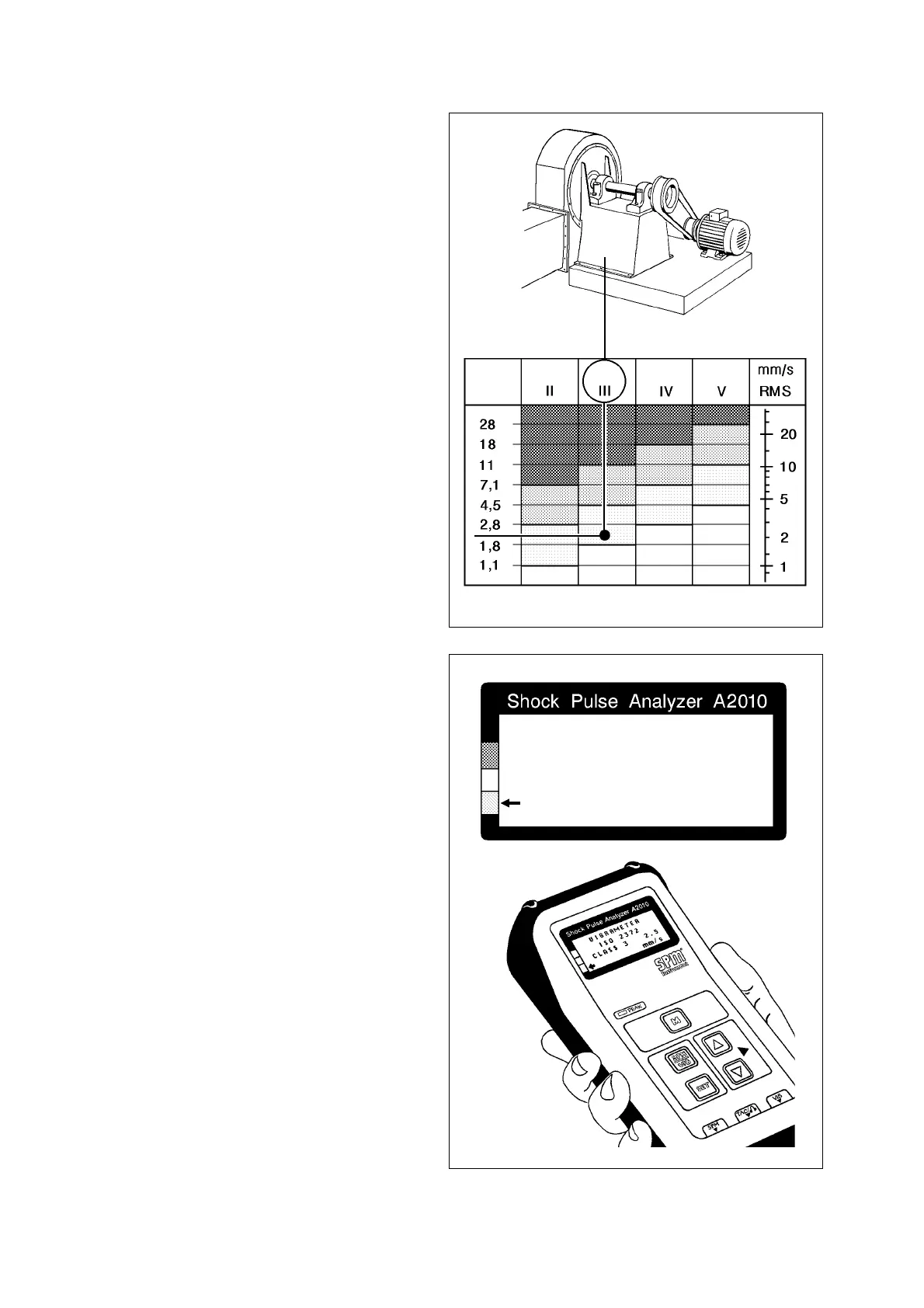
The acceptable vibration level depends on the size,
design, and function of the machine, as well as on the
stiffness of its foundation. ISO recommendation 2372
(likewise BS 4675 and VDI 2056) define vibration clas-
ses for various types of machines. The table in figure
26 shows the most common of the six classes and
their limit values.
In order to assess machine condition on the basis of
vibration severity measurements, one has to define
the normal vibration level of the machine, either ac-
cording to its vibration classing, the manufacturer’s
recommendations, or on the basis of measurements
when the machine is in good condition.
As an example, a 100 kW ventilation fan on a concrete
base would belong to class III. If the number 3 is input
prior to measurement, the A2010 will compare the
measuring result with the limit values for this class. An
arrow pointing at the condition scale will indicate
machine condition in terms of good - reduced - bad. If
no class number is input, the vibration severity value
will be shown without further evaluation.
Vibration measuring points are usually selected on
the bearing housings. The vibration transducer is sen-
sitive only along its main axis, in the direction it is
pointed.
This allows a limited analysis of the causes for excess-
ive vibration. Radial vibration, measured in the verti-
cal direction, gives information about structural weak-
ness, whereas a horizontal reading is most repre-
sentative of balance conditions. Axial vibration, along
the line of the shaft, is normally caused by faulty
alignment, badly assembled couplings or bent shafts.
Thus, readings from several measuring points in three
directions can usually give a good indication of the
nature and location of the maintenance problem.
Vibration Severity Measurement
Fig. 27
Fig. 26
Limits Class Class Class Class
VIBRAMETER
ISO 2372
CLASS 3 2.5
mm /s