68
Technical data are subject to change without notice.
ISO 9001 certified. © Copyright SPM 1996-9. 71411.B
SPM Instrument AB • Box 4 • S-645 21 Strängnäs • Sweden
Tel +46 152 22500 • Fax +46 152 15075 • info@spminstrument.se • www.spminstrument.se
Calculating the Correction Mass
To illustrate the procedure we use the following val-
ues as an example:
Trial weight: M
t
= 12.3 grams
Vibration without weight: V
0
= 6.1 mm/s
Trial weight at point 1: V
1
= 7.7 mm/s
Trial weight at point 2: V
2
= 3.2 mm/s
Trial weight at point 3: V
3
= 10.3 mm/s
We are looking for the following values:
V
t
= dividing factor for the calculation
M
b
= correction mass in grams
α = angular position of the mass.
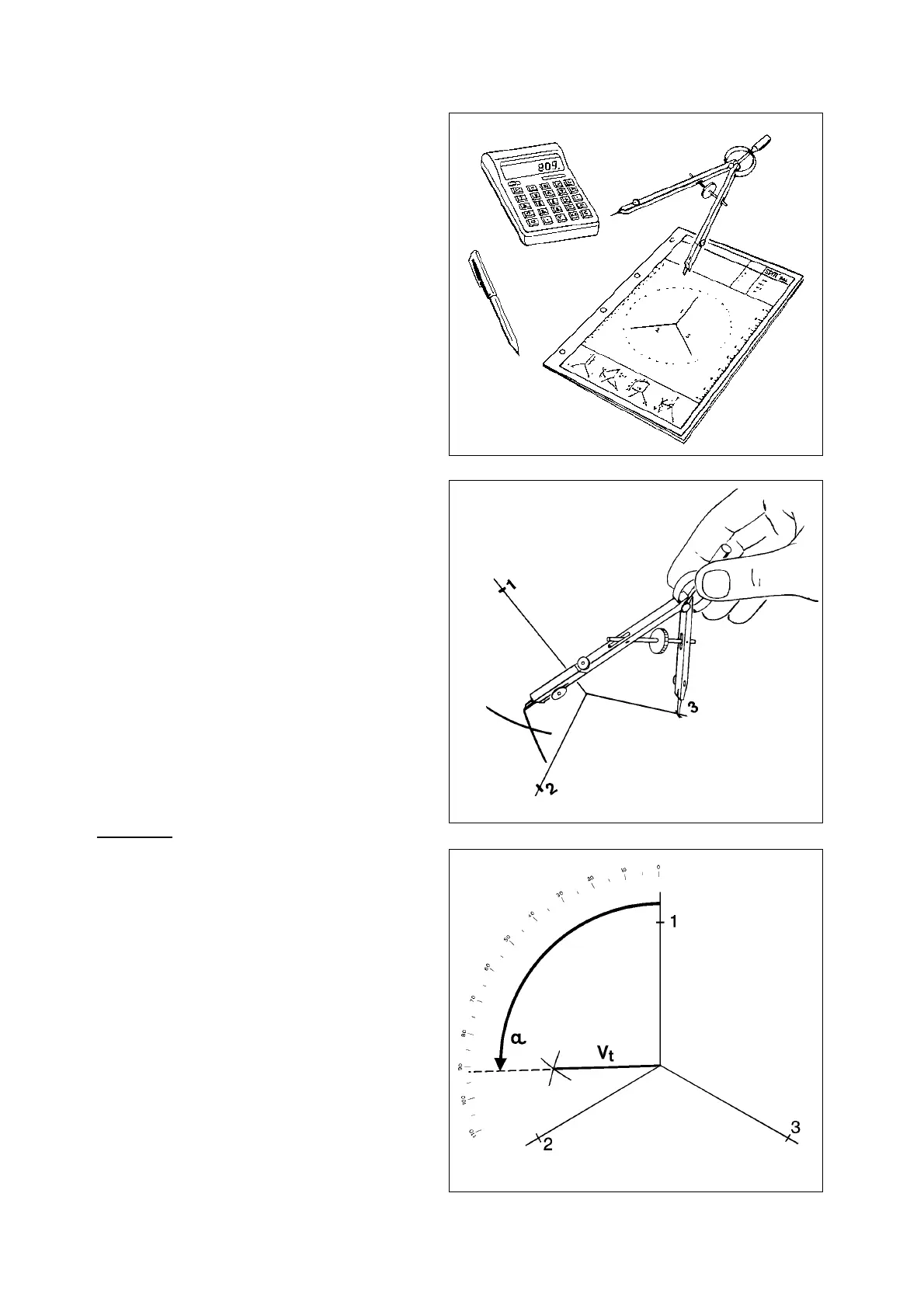
Choose a suitable scale on the SPM balancing form.
Use the compasses to mark off V
0
(= 6.1) on each of
the three printed lines. This gives you three points at
equal distance from the origin of the figure, which are
numbered counter clockwise 1, 2 and 3.
Compare the readings from the three runs with trial
weight. In our example, V
3
and V
1
are both larger than
V
2
. The weight of the correction mass always depends
on the two highest readings (the third helps to define
its position).
Draw an arc with radius V
3
, the highest value (= 10.3),
from point 3 towards point 2. Then draw an arc with
radius V
1
, the second highest value (= 7.7), from point
1 so that it intersects the first arc.
Measure the distance (same scale) between the point
of intersection and the origin of the figure. This dis-
tance (= 4.6) is the divisor V
t
for the equation below.
The equation for the weight of the correction mass is:
M
t
x V
0
=M
b
V
t
In our example, the figures are 12.3 x 6.1 / 4.6 = 16.3
(grams). We need a correction mass weighing 16.3
grams.
Position of the Mass
Measure the angle between the lines V
1
and V
t
(always
these two, and always measure from V
1
to V
t
counter
clockwise). The correction mass is attached to the
rotor at this angle (here 91°) measured counter clock-
wise from trial point 1, and at the same radial distance
from the shaft as the trial weight.
Fig. 18
Fig. 20
Fig. 19