5
Technical data are subject to change without notice.
ISO 9001 certified. © Copyright SPM 1996-9. 71411.B
SPM Instrument AB • Box 4 • S-645 21 Strängnäs • Sweden
Tel +46 152 22500 • Fax +46 152 15075 • info@spminstrument.se • www.spminstrument.se
BEARING TEST
CODE A
LUB 2
COND 28
Acc 3/3
LR 24
HR 20
M
Shock Pulse Analyzer A2010
SPM
TAC / Ω
VIB
SPM
VIB
SET
PEAK
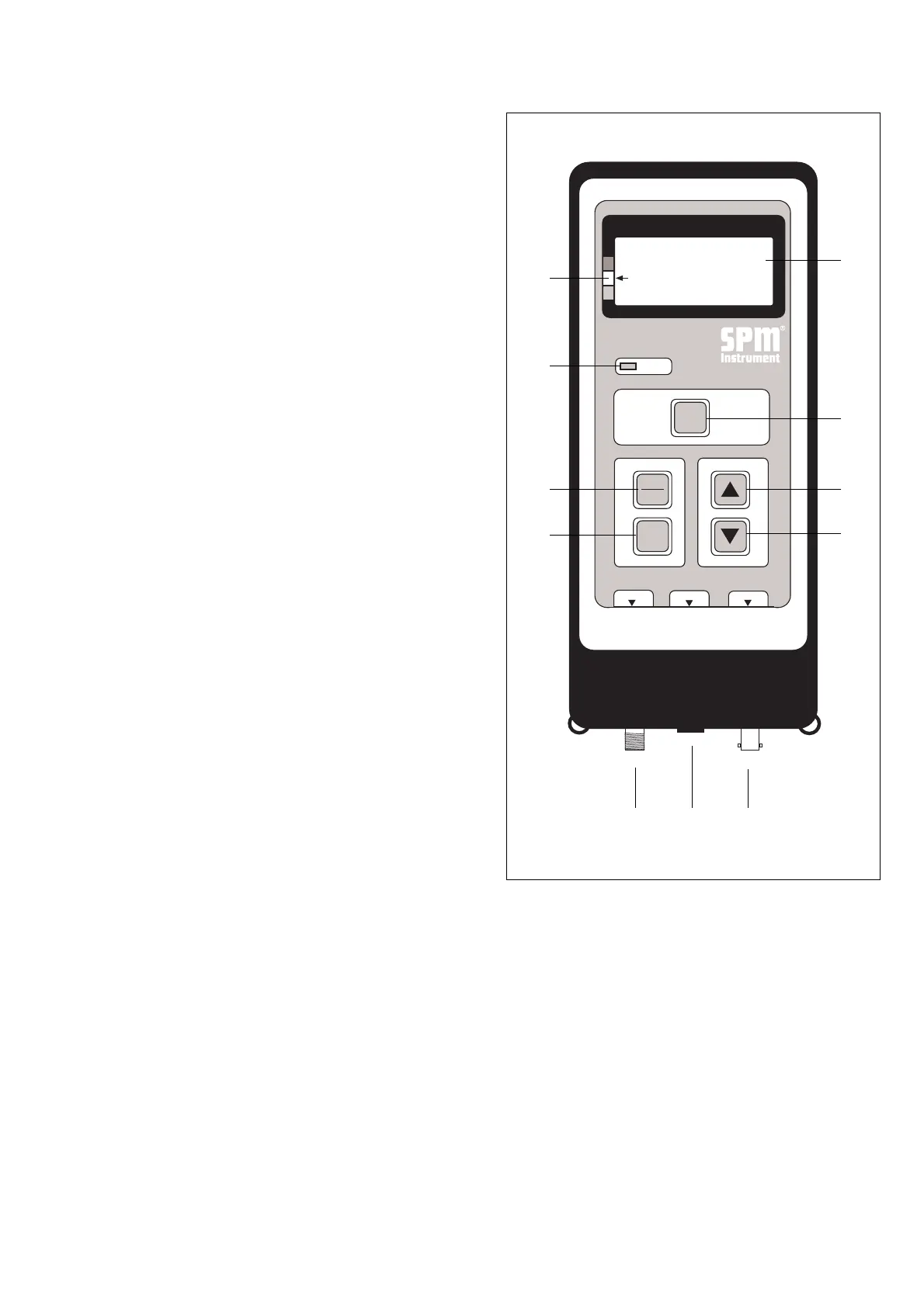
The A2010 has three inputs, each with a different
connector type, and specialized circuits for all three
measuring functions. Only five control keys are needed
to operate the instrument. Two unmarked keys pro-
vide master reset (12) and a display of the program
version number (13).
1 LCD Display
On four lines, the display shows menus, selected mea-
suring mode, input data, and measuring results.
2 Condition Scale
An arrow pointing at the green, yellow, or red field of
the condition scale provides an instant evaluation of
the measured shock pulse or vibration level:
green = good condition
yellow = reduced condition
red = bad condition.
3 Peak Indicator
In the earphone mode, a blinking light shows the
existence of shock pulse peaks above the displayed
shock level.
4 Measuring Key
The M key starts the measurement. For continuous
vibration measurement, the key is held down.
5 Select Key
The SPM/VIB key switches from shock pulse to vibra-
tion measurement and back.
6 Set Key
The SET key initiates the setting of input data and
earphone volume.
7/8 Arrow Keys
The arrow keys are used to increase (7) or decrease
(8) the values of input data and to change measuring
thresholds in the earphone mode.
9 Input for Shock Pulse Transducer
A threaded connector receiving the coaxial cable from
a hand-held probe, a transducer with quick connec-
tor, or a measuring terminal.
7
3
5
6
4
8
91011
1
2
Instrument Keys and Functions
10 Input for Earphone, Tachometer
Connecting the earphone or the tachometer probe
will switch the A2010 to the respective measuring
mode.
11 Input for Vibration Transducer
A bayonet connector receiving the coaxial cable from
the vibration transducer.
Fig. 2