49
Technical data are subject to change without notice.
ISO 9001 certified. © Copyright SPM 1996-9. 71411.B
SPM Instrument AB • Box 4 • S-645 21 Strängnäs • Sweden
Tel +46 152 22500 • Fax +46 152 15075 • info@spminstrument.se • www.spminstrument.se
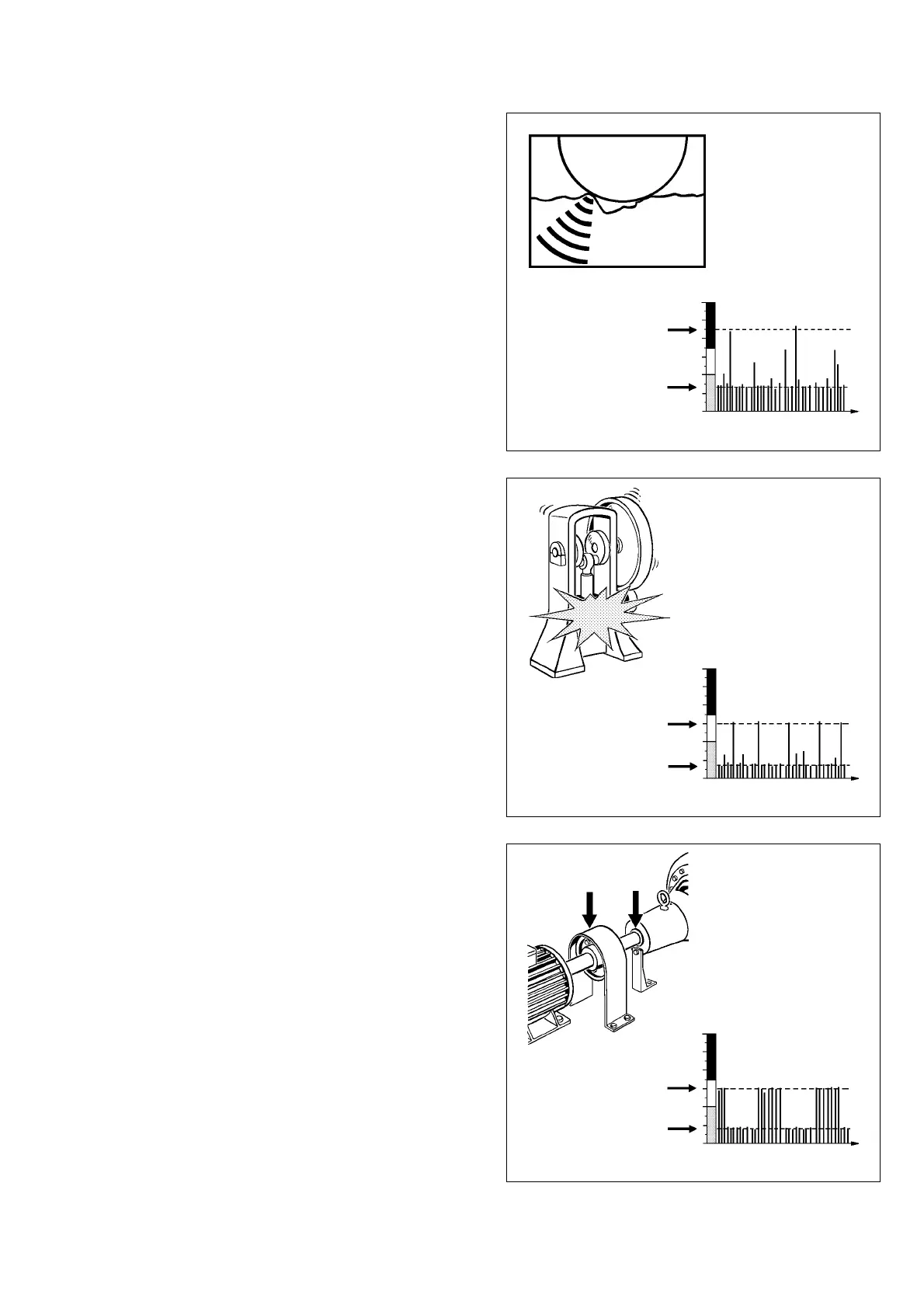
Signal from a Damaged Bearing
Fig. 30
Fig. 32
The pattern shown in figure 30 is typical for damaged
bearing surfaces: CODE D, high LR/HR readings with
a large delta, and a random pattern of strong pulses.
The COND No. indicates the degree of damage:
COND No. < 30 Slight damage
COND No. 30 - 40 Increasing damage
COND No. > 40 Severe damage.
Note: a similar pattern is caused by contaminations in
the lubricant (metal or dirt). The particles either origi-
nate from parts of the bearing itself, for instance from
a damaged cage, or they are transported by the lubri-
cant into the (undamaged) bearing. Test bearing and
lubricant according to the description on page 52.
Rhythmical Peaks
Figure 31 shows a shock pulse pattern with single,
rhythmical peaks. Single peaks can be caused by load
and pressure shocks which occur during the machine's
normal operation. Other possible causes are clicking
valves or loose parts knocking regularly against the
machine frame.
If the signal is strongest on the bearing housing, you
can suspect a cracked inner ring (see page 51).
Periodic Bursts
Periodic bursts are a typical interference signal, caused
by rubbing between machine parts, e.g. shaft against
bearing housing or seal. The burst occurs at an r.p.m.
related frequency.
Fig. 31