40
Technical data are subject to change without notice.
ISO 9001 certified. © Copyright SPM 1996-9. 71411.B
SPM Instrument AB • Box 4 • S-645 21 Strängnäs • Sweden
Tel +46 152 22500 • Fax +46 152 15075 • info@spminstrument.se • www.spminstrument.se
Machine Units and Measuring Rounds
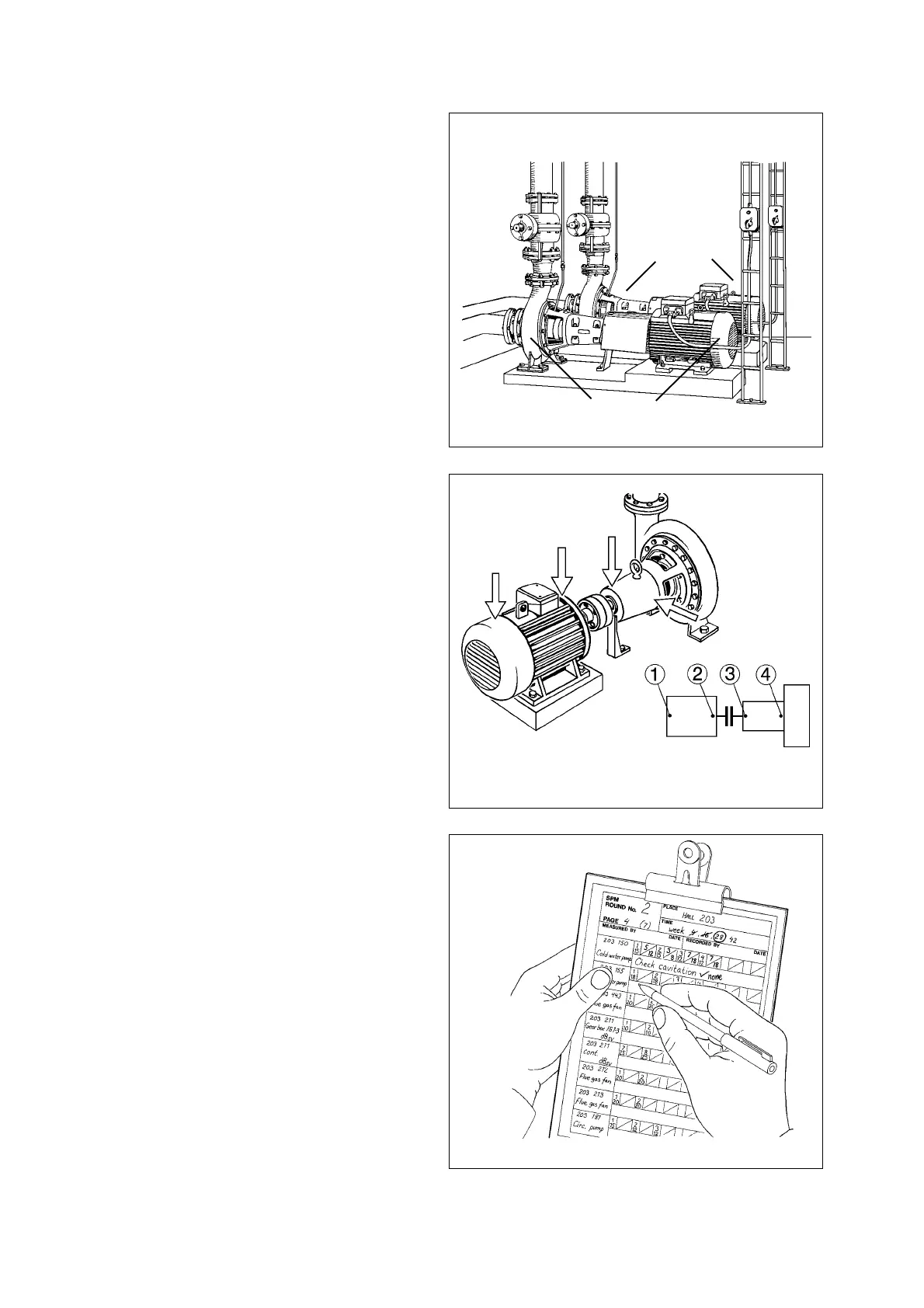
The object of conditon monitoring should always be
the whole machine unit, i. e. the driving and the driven
part as well as the transmission, if any.
If for example the equipment consist of a number of
motors and pumps, as in figure 9, prepare a separate
follow-up form for each motor-pump unit.
One reason for this is that poor shaft alignment nor-
mally affects the bearings on both sides of the cou-
pling, and is easily recognized when the readings for
bearings 2 and 3 are recorded on the same form.
The exception are very large machines, such as paper
machines, where the bearings on the drive end of a
section's cylinders are usually treated as one unit, and
the bearings on the non-drive end as another.
Names and Numbers
Use a consistent naming and numbering system to
make it easy to recognize the machine unit and the
measuring points on follow-up forms and check lists.
Common practice is to start measuring point number-
ing at the fan end of the motor (1) and continue along
the line of power transmission:
Point 1: Motor N (non-drive end)
Point 2: Motor D (drive end)
Point 3: Pump D
Point 4: Pump N
Plan Measuring Rounds
A catalogue of plant machinery, floor plans, and ma-
chine drawings are useful planning aids.
Select the machines which are important for produc-
tion and safety. Divide the machines you want to
monitor into groups which can be measured on one
occasion. Find out the shortest route between meas-
uring points.
A check list of the machines to be measured on one
measuring round is easier to carry than a folder of
follow-up forms. The check list should have space for
one reading per measuring point and for notes.
Fig. 9
Fig. 10
Fig. 11
Machine unit A
Machine unit
B