37
Technical data are subject to change without notice.
ISO 9001 certified. © Copyright SPM 1996-9. 71411.B
SPM Instrument AB • Box 4 • S-645 21 Strängnäs • Sweden
Tel +46 152 22500 • Fax +46 152 15075 • info@spminstrument.se • www.spminstrument.se
The clicking of valves, high pressure steam flow, me-
chanical rubbing, damaged or badly adjusted gears,
and load shocks from machine operation can cause a
general high shock level on the machine frame. This
interference can mask the bearing signal in cases where
• the shock level measured outside of the bearing
housings is as high as or higher than the shock
level on the bearing housings.
Remove Sources of Interference
In most cases, interference is the result of bad ma-
chine condition. For example – cavitation in a pump is
due to flow conditions for which the pump was not
designed. Cavitation does more than interfere with
bearing monitoring – it slowly erodes the material of
the pump.
Monitoring the bearings is pointless if the machine
breaks down or requires frequent repairs because of
other poorly maintained parts or badly adjusted oper-
ating parameters. Therefore,
• do not accept interference – try to remove the
cause.
Use the SPM readings to detect the source. Pages 48
to 51 contain typical shock pulse signals from various
sources.
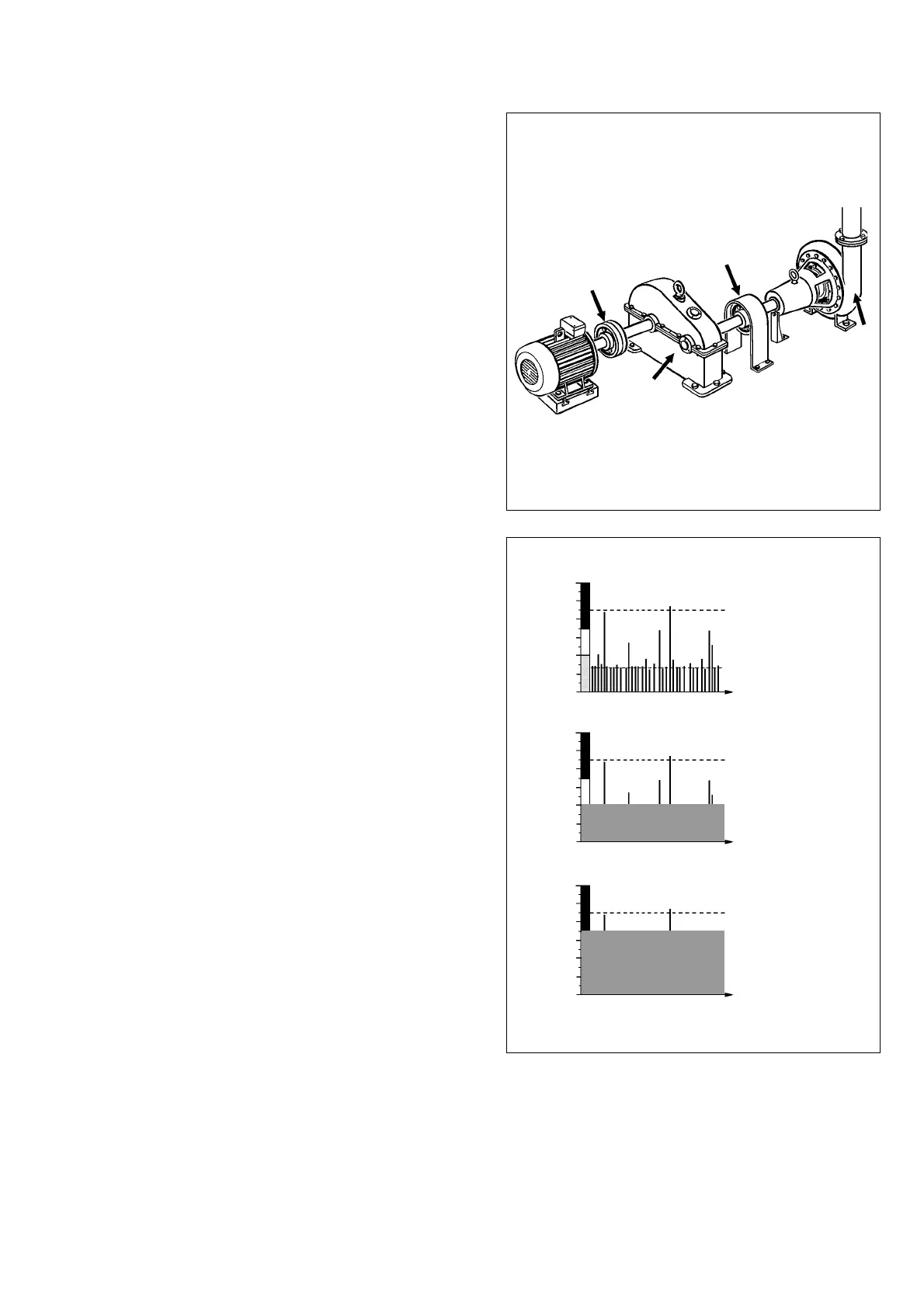
Coping with Interference
If the source of interference cannot be removed, there
are several possibilities:
• If it is intermittent, measure while there is no
interference.
If interference is persistent, measure its shock pulse
level with the same setting as the bearing and com-
pare it with the condition zones:
• If interference masks the green zone, you can get
true bearing condition readings in the yellow and
red zone.
• If interference masks the yellow zone, you can get
true bearing condition readings in the red zone,
i.e. find a damaged bearing.
If the interference level is persistently higher than the
shock level that would be caused by bad bearing
condition (you can check that with LUBMASTER), do
not try to monitor the bearing.
Create Acceptable Measuring Conditions
Fig. 3
Fig. 4
No
interference
Low level
interference
High level
interference
Alignment
Scraping,
alignment
Cavitation
Gear tooth
damage