28
Technical data are subject to change without notice.
ISO 9001 certified. © Copyright SPM 1996-9. 71411.B
SPM Instrument AB • Box 4 • S-645 21 Strängnäs • Sweden
Tel +46 152 22500 • Fax +46 152 15075 • info@spminstrument.se • www.spminstrument.se
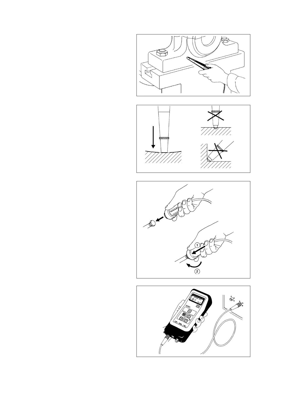
All three types of shock pulse transducers are con-
nected to the TNC connector marked SPM. The choice
of transducer type depends on how the measuring
point is prepared. For systematic shock pulse moni-
toring, SPM recommends the use of installed adap-
ters and quick connect transducer wherever possible.
The selection and preparation of measuring points is
described in the next chapter.
Transducer with Probe
The probe is directionally sensitive. It has to be pointed
straight at the bearing.
The probe tip is spring loaded and moves within a
sleeve of hard rubber. To maintain a steady pressure
on the tip, press the probe tip against the measuring
point until the rubber sleeve is in contact with the sur-
face.
Hold the probe steady to avoid rubbing between
probe tip and surface.
The centre of the probe tip should touch the surface.
Avoid pressing the probe tip against cavities and
fillets which are smaller than the probe tip.
Transducer with Quick Connector
Make sure that the adapter's contact surface is clean.
Apply a small amount of clean grease or oil to the
surface to improve signal transmission.
To attach the transducer, push it hard onto the adapter
and twist it clockwise to stop. To unfasten the trans-
ducer, push it hard against the adapter and twist
counter clockwise. Replace the adapter cap after tak-
ing the reading.
Measuring Terminals
Connect a coaxial cable between A2010 and the mea-
suring terminal. Replace the dust cap on the terminal
after the reading.
Shock Pulse Transducers
Fig. 17
Fig. 16
Fig. 15
Fig. 14