P340 flexiprobe Operation Manual 3
Section 2: System Overview
The P340 flexiprobe pushrod inspection system comprises of a controller, pushrod reel, camera and
accessories. This subsection provides a detailed, illustrated overview of these components.
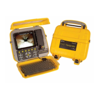
2.1 Controller
The P340 command module unit acts as the controller and digital video recorder and playback device.
Video is displayed on an 8" industrial LCD. Video, pictures and inspection reports are stored on a
compatible high-speed Compact Flash card or USB flash drive. See Figures 2.1 to 2.3.
1. On/Off Switch: Switches power ON or OFF.
2. Keypad and function keys: Allows the operator to control the system, select functions and edit
text entries.
3. Keyboard: Provides enhanced text entry capabilities and shortcuts to access system functions.
4. Display: LCD Screen shows video, still images and various on-screen system information.
5. Link cable socket: To connect the pushrod reel to the controller with a link cable.
6. Controller support clamp: To mount the controller onto the reel (optional on the Mini model).
7. Fuse holder: 5mm x 20mm T3.15A 250V cartridge fuse.
8. VIDEO IN and VIDEO OUT Connectors (RCA Video Jacks): Provide secondary input and
output options for external composite video equipment.
9. Power socket: DC power input from vehicle supply, internal or external batteries (optional), or
mains adaptor.
10. On/off switch: Switches power ON or OFF.
11. Audio socket: Connects the optional headset to record/playback audio over videos.
12. USB socket: The controller can use a USB flash drive to store video recordings, reports and
pictures. Most stored files can be viewed or played on the controller or transferred to PC. Also
used to store and upload software upgrades
13. Internal battery power port and charger (P340+ only). Dual-use connector, used to supply
power to the controller, or charge the internal battery.
14. PC socket. USB (type B) connection to transfer files to computers.
15. Keyboard socket: Connects the keyboard
16. Compact Flash card slot: The controller can use a Compact Flash card to store video
recordings, reports and pictures. Most stored files can be viewed or played on the controller or
transferred to PC. Also used to store and upload software upgrades.
17. Battery status indicator (P340+ only): Provides an estimation of the internal battery charge
when the Battery Check button (item 18) is pressed.