P340 flexiprobe Operation Manual 9
Section 4: System Assembly
This Section describes the procedures used to setup the P340 flexiprobe for the first time. The system can
be configured in a large number of ways, depending on the components you have chosen for your survey.
Unless indicated otherwise, most of the procedures do not need to be repeated unless the P340 controller
is reset to factory settings.
WARNING! Before attempting to assemble the system, ensure to switch off the controller power.
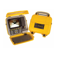
4.1 Controller
4.1.1 Mounting
The controller can be mounted on the optional support stand. If required, see Section 11.2 for a detailed
guide on how to install the clamp assembly. The P343 has an integrated structural bracket.
4.1.2 Power
WARNING! The controller is not earthed. If system connects to any mains operated equipment, the
external equipment MUST BE earthed in accordance with the manufacturer’s instructions. Failure to earth
the attached equipment may result in potentially lethal electric shock.
Release the side catches and open the two covers.
Ensure the On/Off switch (item 10 in Figure 2.3) is set to the Off position.
Open the I/O panel cover.
Connect the power supply (12-24V DC vehicle supply, mains adaptor or optional battery pack) to
the power socket. (Item 9 in Figure 2.3).
CAUTION Use only the supplied mains adaptor; using other adaptors may damage the system.
4.1.3 Compact Flash card
Insert a compatible Compact Flash card into the card slot, which is located inside the I/O panel (Item 16 in
Figure 2.3).
Please note the orientation of the card before attempting to insert it into the controller. Although a groove
on the card will prevent you from inserting the card the wrong way, forcing this will damage the Compact
Flash card socket.
For more information about Compact Flash cards refer to Section 7.1.
4.1.4 USB flash drive
Insert a compatible USB flash drive, (commonly known as a memory stick or thumb drive) into the USB
socket, which is located inside the I/O panel (Item 12 in Figure 2.3).