76 MS 200, MS 200 T
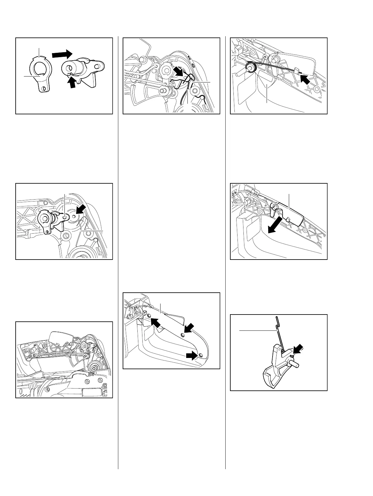
: Position the choke lever (1) so
that the lug (2) engages the slot
(arrow).
– Push the choke lever (1) on to the
shaft.
– Push the contact spring (1) to the
side.
: Push the switch shaft, pin (2) first,
into its mount (arrow).
– Install the throttle trigger and
interlock lever, b 12.3
– Install the choke and throttle
rods, b 12.3.2
162RA019 TG
1
2
162RA020 TG
– Check operation.
– Fit the control lever to simplify
selection of the switch positon.
: Move switch shaft to "
0" – the
contact springs (1+2) must touch
the switch shaft's pin (arrow) –
contact is made.
The throttle trigger and interlock
lever may pop out.
– Reassemble all other parts in the
reverse sequence.
– Tightening torques, b 3.5
12.2 Throttle Trigger/Interlock
Lever (MS 200)
: Take out the screws (arrows).
– Remove the handle molding (1).
The throttle trigger and interlock
lever may pop out.
1
2
162RA021 TG
1
161RA250 TG
: Disconnect the torsion spring
from the interlock lever (arrow).
– Pull the throttle trigger (1) out of
the handle housing and throttle
rod.
: Remove the interlock lever (1).
– Check the individual parts and
replace if necessary.
: Attach the torsion spring (1) to
the throttle trigger
– note installed position (arrow).
1
161RA251 TG
1
161RA252 TG
1
161RA421 TG

 Loading...