5 | Technical data STOBER
22
03/2020 | ID 442793.03
5.1.6 Electrical data
The electrical data of the available SC6 sizes as well as the properties of the brake chopper can be found in the following
sections.
Information
For the time span between two energizing processes, note that:
▪ Direct, repeat activation of the supply voltage is possible for power-on/power-off operation.
▪ A time span of > 15 must be observed between two energizing processes during continuous, cyclical power-on/
power-off operation with increased charging capacity.
Information
The STO safety function is available for safe stopping as an alternative to continuous, cyclical power-on/power-off
operation.
An explanation of the formula symbols used can be found in the chapter Symbols in formulas [}92].
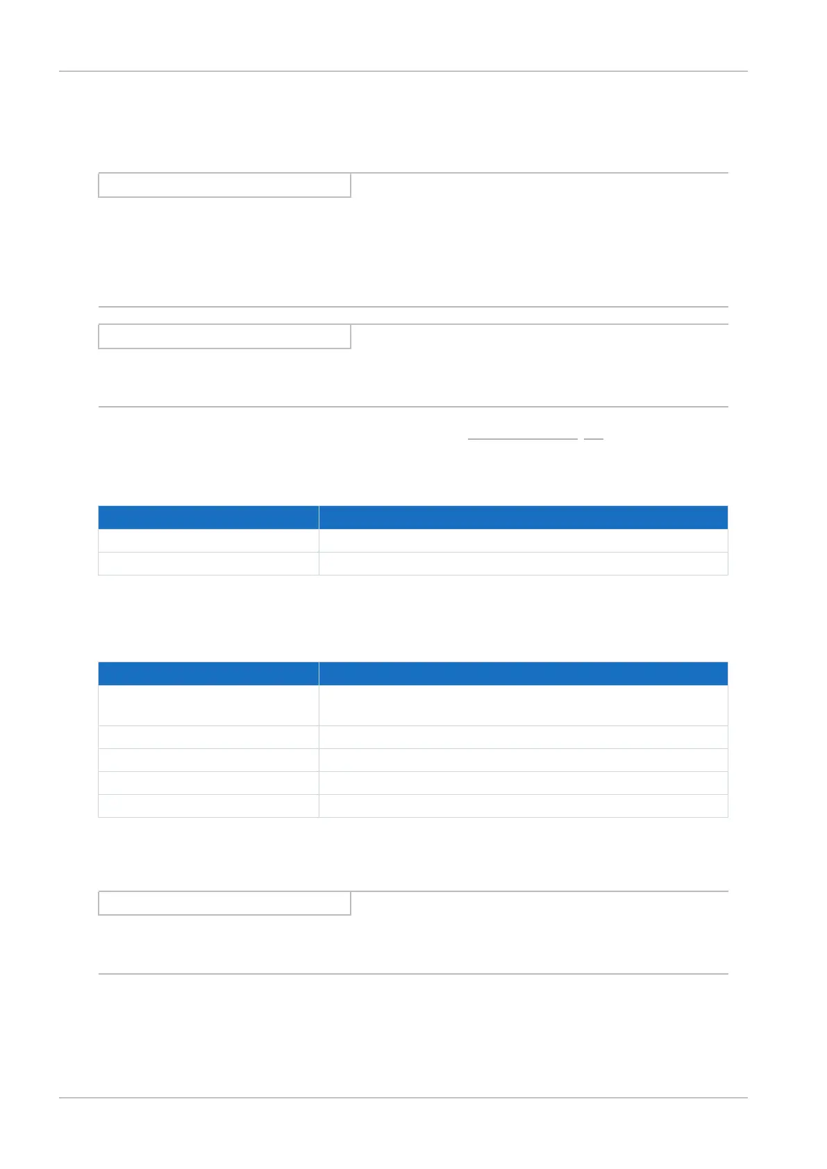
5.1.6.1 Control unit
Electrical data All types
U
1CU
24V
DC
, +20%/−15%
I
1maxCU
0.5A
Tab. 13: Control unit electrical data
5.1.6.2 Power unit: Size 0
Electrical data SC6A062
U
1PU
3 × 400V
AC
, +32% / −50%, 50/60 Hz;
3 × 480V
AC
, +10% / −58%, 50/60Hz
f
2PU
0 – 700 Hz
U
2PU
0 – max. U
1PU
C
PU
270µF
C
maxPU
1400µF
Tab. 14: SC6 electrical data, size 0
The maximum charging capacity depends on the time between energizing two devices:
Information
If a time span of ≥ 15min is maintained between energizing two devices, the maximum charging capacity C
maxPU
increases to
1880μF.
 Loading...


