7 | Installation STOBER
38
03/2020 | ID 442793.03
7.7 Installing the DC link connection
WARNING!
Electrical voltage! Risk of fatal injury due to electric shock!
▪ Always switch off all power supply voltage before working on the devices!
▪ Note the discharge time of the DC link capacitors in the general technical data. You can only determine the absence
of voltage after this time period.
Tools and material
You will need:
§ 3 copper rails with sufficient length and a cross-section of 5 x 12mm, see the chapter Length of copper rails [}36]
§ The nut and washer assemblies (M5) as well as the quick fastening clamps included with the DL6B Quick DC-Link
modules
§ The insulation end sections for the left and right termination of the group that are available separately
§ Fastening screws and tool for tightening the fastening screws
Requirements and installation
Perform the following steps in the specified order.
ü
You have tapped holes for fastening screws on the mounting plate at the installation location in accordance with the
drilling diagram and taking into consideration the different device dimensions.
ü
The mounting plate has been cleaned (free of oil, grease and swarf).
ü
The copper rails must be straight, smooth, free of burrs and cleaned (free of oil and grease).
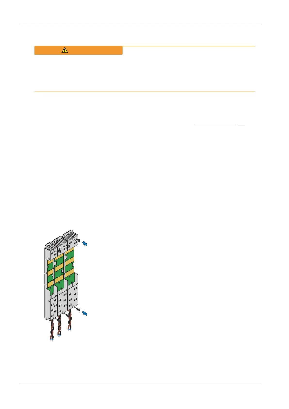
1. Fasten the Quick DC-Link modules onto the mounting plate with the fastening screws.
 Loading...


