STOBER 8 | Connection
03/2020 | ID 442793.03
63
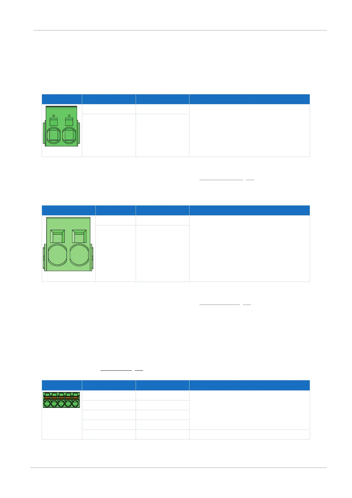
8.4.15 X22: DC link connection
Terminal X22 is available for the DC link connection of the drive controller.
For setting up the Quick DC-Link, note the information on project configuration in the manual for the SC6 drive controller.
Size 0
Terminal Pin Designation Function
1 | 2
1 D− DC link connection
2 D+
Tab. 72: X22 connection description, size 0
For connecting wiring, observe the terminal specifications in the chapter ISPC 5 -STGCL-7,62 [}88].
Sizes 1 and 2
Terminal Pin Designation Function
1 | 2
1 D− DC link connection
2 D+
Tab. 73: X22 connection description, sizes 1 and 2
For connecting wiring, observe the terminal specifications in the chapter ISPC 16 -ST-10,16 [}88].
8.4.16 X101: DI1 – DI4
Digital inputs 1 to 4 are available at terminal X101.
X101 for digital signals
For evaluating digital signals at X101, note the specification for the digital inputs in the technical data of the drive
controller; see the chapter Digital inputs [}26].
Terminal Pin Designation Function
5|4|3|2|1
1 DI1 Digital inputs
2 DI2
3 DI3
4 DI4
5 DGND Reference ground; not bridged with X103, pin 5
Tab. 74: X101 connection description for digital signals
 Loading...


