STOBER 8 | Connection
03/2020 | ID 442793.03
47
DANGER!
Electrical voltage! Risk of fatal injury due to electric shock!
Leakage currents with a DC current component may occur in 3-phase installations.
▪ Always protect 3-phase installations with type B residual current protective devices, sensitive to all currents.
False triggering – Causes
Depending on stray capacitances and imbalances, leakage currents above 30mA may occur during operation. Undesirable
false triggering occurs under the following conditions:
§ When connecting installations to the supply voltage. This false triggering can be rectified by using short-time delayed
(super-resistant), selective (delayed switch-off) RCDs or RCDs with increased trigger current (e.g. 300 or 500mA).
§ Due to higher frequency leakage currents for long power cables under normal operating conditions. This false
triggering can be rectified using low-capacitance cables or an output choke, for example.
§ Due to imbalances in the supply grid. This false triggering can be rectified, e.g. using an isolating transformer.
Information
Check whether the use of residual current protective devices with increased trigger current as well as with short-time
delayed or delayed switch-off trigger characteristics are permitted in your application.
DANGER!
Electrical voltage! Risk of fatal injury due to electric shock!
Leakage and residual currents with a DC current component can restrict the functionality of type A and AC residual current
protective devices.
▪ Always follow the installation instructions for the protective devices you are using.
8.3.3 Protective grounding
Observe the requirements described below for the correct connection of the protective grounding.
8.3.3.1 Minimum cross-section of the grounding conductor
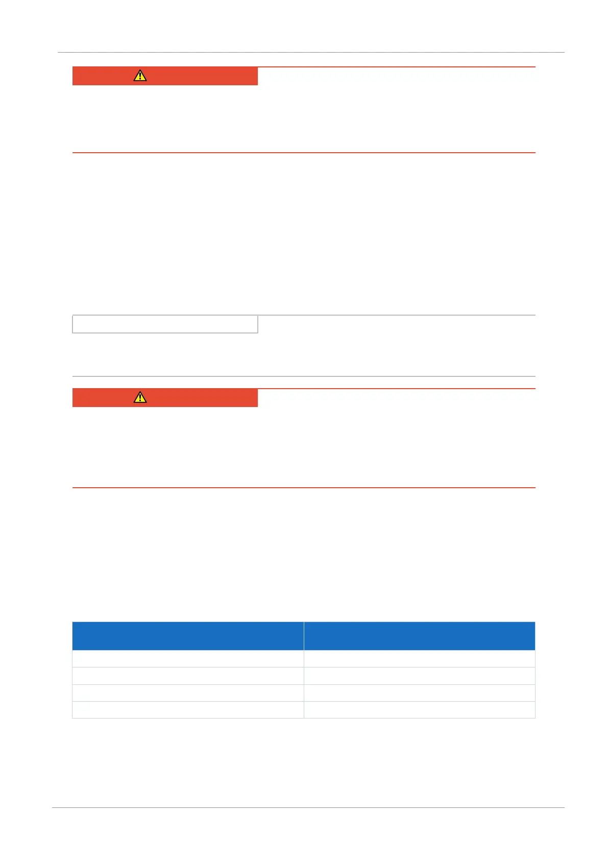
Leakage currents > 10mA can arise in normal operation. To fulfill local safety regulations such as DIN EN 60204-1, connect
the grounding bolt with a copper conductor according to the following table:
Cross-section A
Power grid line
Minimum cross-section A
min
Grounding conductor at grounding bolt
A ≤ 2.5mm² 2.5mm²
2.5 < A ≤ 16mm² A
16 – 35 mm² ≥ 16 mm²
> 35 mm² A/2
Tab. 45: Minimum cross-section of the grounding conductor
 Loading...


