STOBER 11 | Appendix
03/2020 | ID 442793.03
89
11.2 Wiring examples
The following chapters show the basic connection using examples.
Information
For UL-compliant operation: The connections marked with PE are intended solely for the functional grounding.
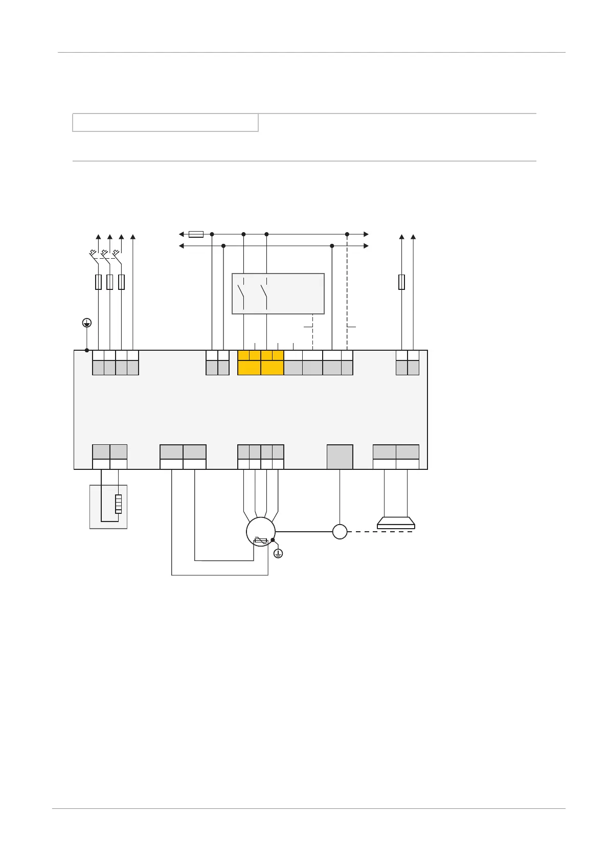
11.2.1 Stand-alone operation with direct brake control
The following graphic shows a wiring example for stand-alone operation with direct brake control.
X10
GND
STO_a
STO_b
GND
Vc
L1
L2
L3
PE
1
2
3 4
1
2
3 4
5
6
7
8
X11
+
-
1
3
F3
K1
M
24 V
DC
X300
+
-
1
3
T1
F2
F1
F4
1
X20A X4A
X2A
1TP1
1TP2
U
V W
PE
7
8
1
2
3
4
n
X2A
1BD1
1BD2
5
6
R1
1
2
RB RB
2
3
4
M
M1
X21
1
PE
L1 L2
L3
24 V
DC
M
STO
status
X12 (option )
Direct
brake
control
D-sub
15p
SC6
ST6
Fig.13: Wiring example with direct brake control
F1 – F4 Fuse
K1 Safety relay
L1 – L3 Three-phase power supply
M Reference ground
M1 Motor
R1 Braking resistor
T1 Supply module
T2 Drive controller
1 Optional connection
For UL-compliant operation:
The protective grounding of motors connected to the drive controller must not be connected using terminals X20A and
X20B. The grounding conductor connection of the motor must be ensured for the respective application in accordance with
the valid electrical standards.
 Loading...


