8 | Connection STOBER
62
03/2020 | ID 442793.03
Shielded connection of the power cable
Note the following points for the connection of the power cable:
§ Ground the shield of the power cable on the shield contact on the drive controller intended for this.
§ Keep the exposed conductors as short as possible. All devices and circuits that are sensitive to EMC must be kept at a
distance of at least 0.3m.
8.4.13 X20B: Motor B
The motor of axis B is connected to X20B for double-axis controllers. Only X20A is available for single-axis controllers. The
connection description of X20B matches the X20A description.
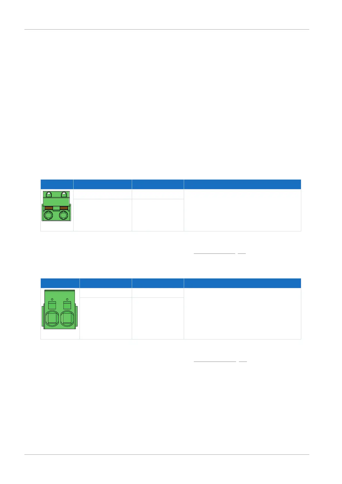
8.4.14 X21: Braking resistor
Terminal X21 is available for the connection of a braking resistor.
Size 0
Terminal Pin Designation Function
1 | 2
1 RB Braking resistor connection
2 RB
Tab. 70: X21 connection description, size 0
For connecting wiring, observe the terminal specifications in the chapter GFKIC 2.5 -ST-7.62 [}87].
Sizes 1 and 2
Terminal Pin Designation Function
1 | 2
1 RB Braking resistor connection
2 RB
Tab. 71: X21 connection description, sizes 1 and 2
For connecting wiring, observe the terminal specifications in the chapter ISPC 5 -STGCL-7,62 [}88].
 Loading...


