STOBER 8 | Connection
03/2020 | ID 442793.03
61
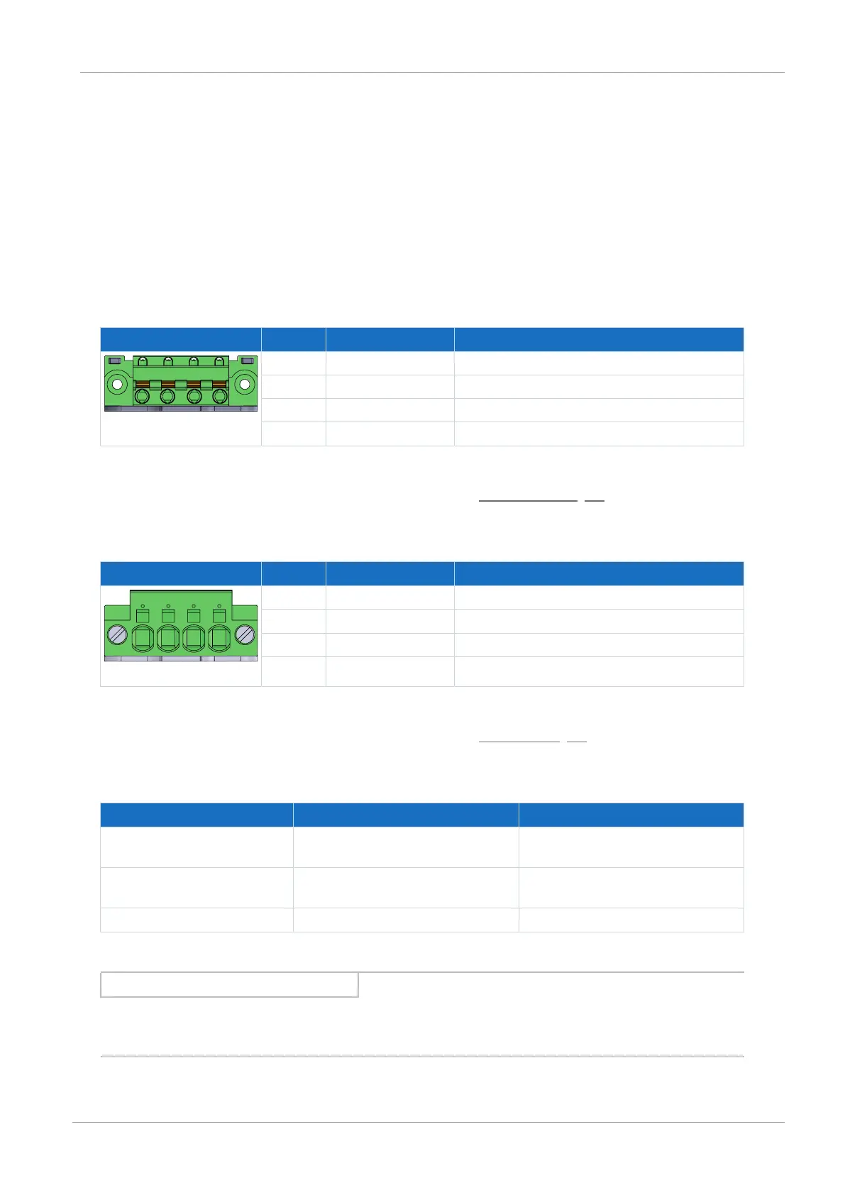
8.4.12 X20A: Motor A
The motor of axis A is connected to X20A.
UL-compliant operation
The protective grounding of motors connected to the drive controller must not be connected using terminals X20A and
X20B. The grounding conductor connection of the motor must be ensured for the respective application in accordance with
the valid electrical standards.
For the protective grounding of the motor, use the grounding conductor connection available on the motor.
Size 0
Terminal Pin Designation Function
1 | 2 | 3 | 4
1 U Motor phase U connection
2 V Motor phase V connection
3 W Motor phase W connection
4 PE Grounding conductor
Tab. 67: X20A connection description, size 0
For connecting wiring, observe the terminal specifications in the chapter GFKC 2,5 -ST-7,62 [}86].
Sizes 1 and 2
Terminal Pin Designation Function
1 | 2 | 3 | 4
1 U Motor phase U connection
2 V Motor phase V connection
3 W Motor phase W connection
4 PE Grounding conductor
Tab. 68: X20A connection description, sizes 1 and 2
For connecting wiring, observe the terminal specifications in the chapter SPC 5 -ST-7,62 [}87].
Cable requirements
Motor type Connection Size 0 to 2
Synchronous servo motor,
asynchronous motor
Without output choke 50m, shielded
Synchronous servo motor,
asynchronous motor
With output choke 100m, shielded
Lean motor Without output choke 50m, shielded
Tab. 69: Maximum cable length of the power cable [m]
Information
To ensure proper functionality, we recommend using cables from STOBER that are matched to the complete system. If
unsuitable connection cables are used, we reserve the right to reject claims under the warranty.
 Loading...


