5 | Technical data STOBER
30
03/2020 | ID 442793.03
5.3 Safety technology
The SR6 option adds the STO safety function to the SC6 drive controller via terminal X12.
For double-axis controllers, the STO safety function has a two-channel structure that acts upon both axes.
Information
If you would like to use the STO safety function via terminals, be sure to read the manual for the SR6 safety module.
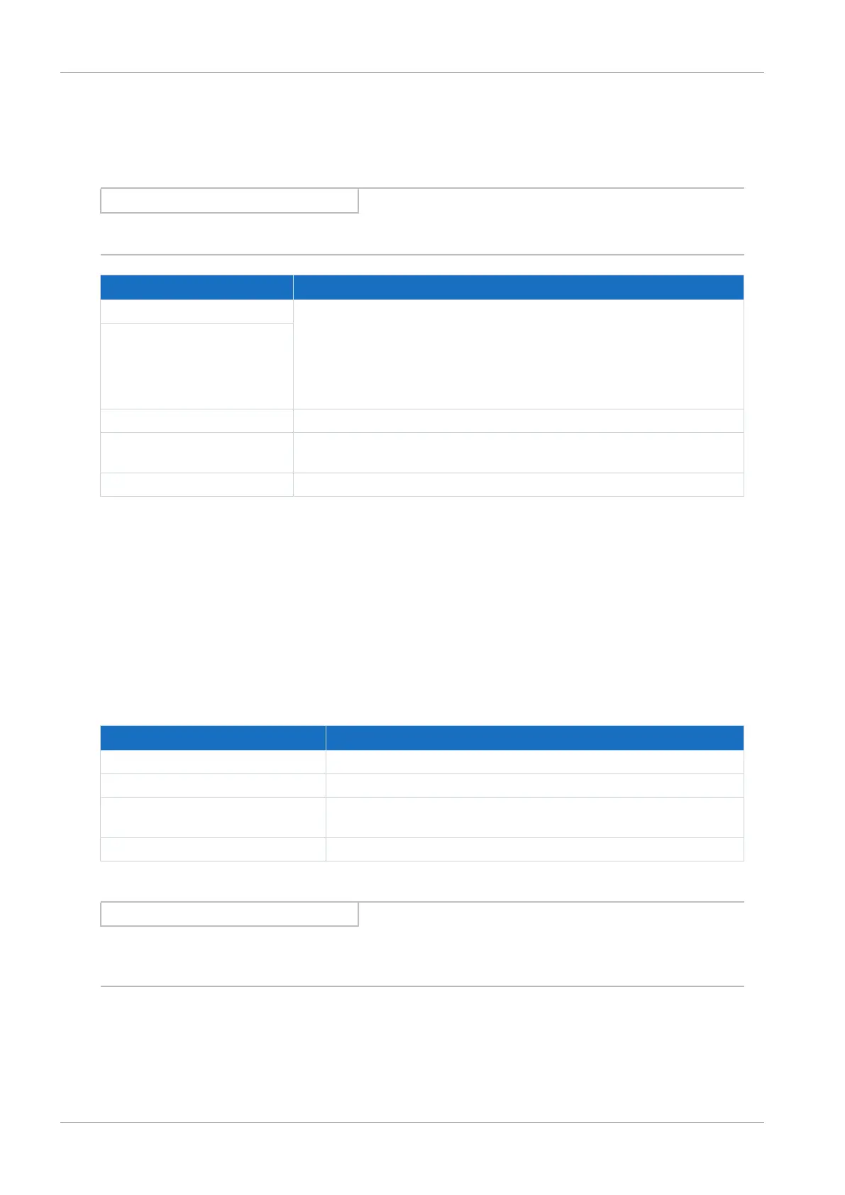
Specification Electrical data
STO
a
U
1max
= 30V
DC
(PELV)
high level = 15 – 30V
DC
low level = 0 – 8V
DC
I
1max
= 100mA (typically < 30mA for 24V
DC
)
I
max
= 4A
C
1max
= 10nF
STO
b
STO
status
U
2
= U
1
− (1.5Ω * I
1
)
STO
status
supply U
1
= +24V
DC
, +20%/25%
I
1max
= 100mA
GND —
Tab. 36: X12 electrical data
5.4 Controllable brakes
The brake of axis A is connected to X2A. Connect the brake of axis B to X2B for double-axis controllers.
You can control the following brakes:
§ Directly connected 24V
DC
brakes
§ Indirectly connected brakes (e.g. over coupling contactor)
The brake is supplied over X300.
Electrical data Brake output
U
2
24V
DC
, +20%
I
2max
2.5A
f
2max
1Hz at I
N
≤ 2.1A;
0.25Hz at I
N
> 2.1A
E
2max
1.83J
Tab. 37: Electrical data of the brake output
Information
In the case of a nominal brake current > 2.1A, the system controller must ensure compliance with the maximum switching
frequency of 0.25Hz.
 Loading...


