STOBER 8 | Connection
03/2020 | ID 442793.03
45
8.3.1.2 Line fuse in parallel connection
Every drive controller connected to the grid in the DC link group must be protected at the line input against overload and
short circuit. To do this, a fuse combination consisting of overload protection and semiconductor short-circuit protection is
connected in series. A miniature circuit breaker protects against overload and a safety fuse with gR triggering characteristics
protects against short circuit.
Information
The installation of short-circuit fuses is not necessary under ideal prerequisites and ambient conditions. However, if the
application conditions pose the risk of contaminating the drive controllers, short-circuit fuses can protect against damage to
or failure of other devices within the DC link group.
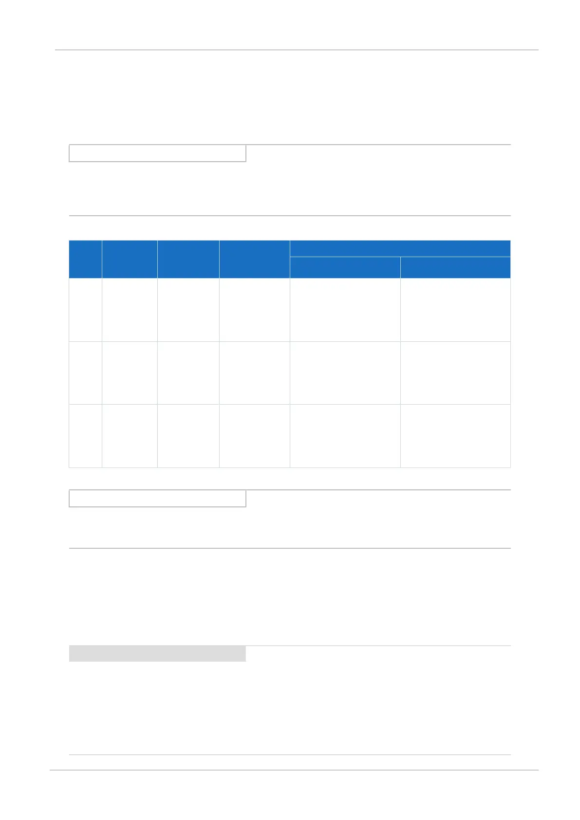
You can use the following fuse combinations:
Size Type I
1N,PU
(4kHz)
[A]
I
1maxPU
(4 kHz)
[A]
Fuse selection
Miniature circuit breakers Safety fuse
0 SC6A062 10 21A EATON
Type: FAZ-Z10/3,
Item No.: 278926
Triggering characteristics:
Z10A
SIBA
Type: URZ,
Item No. 50 140 06.25
Triggering characteristics:
gR25A
1 SC6A162 23.2 48.7A EATON
Type: FAZ-Z25/3,
Item No.: 278929
Triggering characteristics:
Z25A
SIBA
Type: URZ,
Item No. 50 140 06.50
Triggering characteristics:
gR50A
2 SC6A261 22.6 47.4A EATON
Type: FAZ-Z25/3,
Item No.: 278929
Triggering characteristics:
Z25A
SIBA
Type: URZ,
Item No. 50 140 06.50
Triggering characteristics:
gR50A
Tab. 43: Line fuse in parallel connection
Information
To ensure problem-free operation, always comply with the recommended trigger limits and trigger characteristics of the
fuse elements.
Maximum number of drive controllers
Two drive controllers of the same rating can be connected using a common fuse combination. The fuses and the resulting
maximum line input current correspond to that of a single drive controller.
In order to prevent gradual damage to the safety fuse, you can operate a maximum of two drive controllers on one fuse
combination.
ATTENTION!
Damage due to overload!
In order to ensure an even distribution of charging current on all AC-supplied drive controllers, all circuit breakers must be
closed when engaging the power supply.
▪ In order that the input rectifier is not overloaded in the event of a possible fuse failure in the group, evaluation of the
grid monitoring for AC-supplied drive controllers must lead to deactivation of the entire DC link group.
 Loading...


