B58FZS 0000000078 EN 002 112
CONTENTS
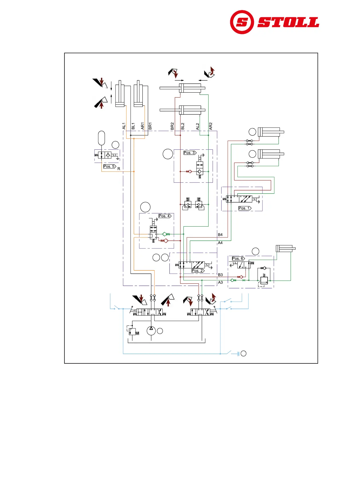
11.4.2 Hydraulics diagram FZ and FZ-L
Fig. 103 Hydraulics diagram FZ and FZ-L
Legend
F1, S1 4th control circuit (optional)
F2, S2 3rd control circuit (optional)
F3a, S3a Quick emptying (only FZ-L)
F4b, S4b Return To Level (only FZ-L)
F5, S5 Comfort-Drive (optional)
F6, S6 Hydro-Lock (optional)
P Tractor pressure
Z Ignition
B04F
210 bar 210 bar
S4b
P
Z
S2 / S3a
S1
B1 A1 A2B2
A2 A1
C2 C1
B2
B1
F2
F1
F3a
F5
F4b
F1F2
F6
150 bar