113 B58FZS 0000000078 EN 002
TECHNICAL SPECIFICATIONS
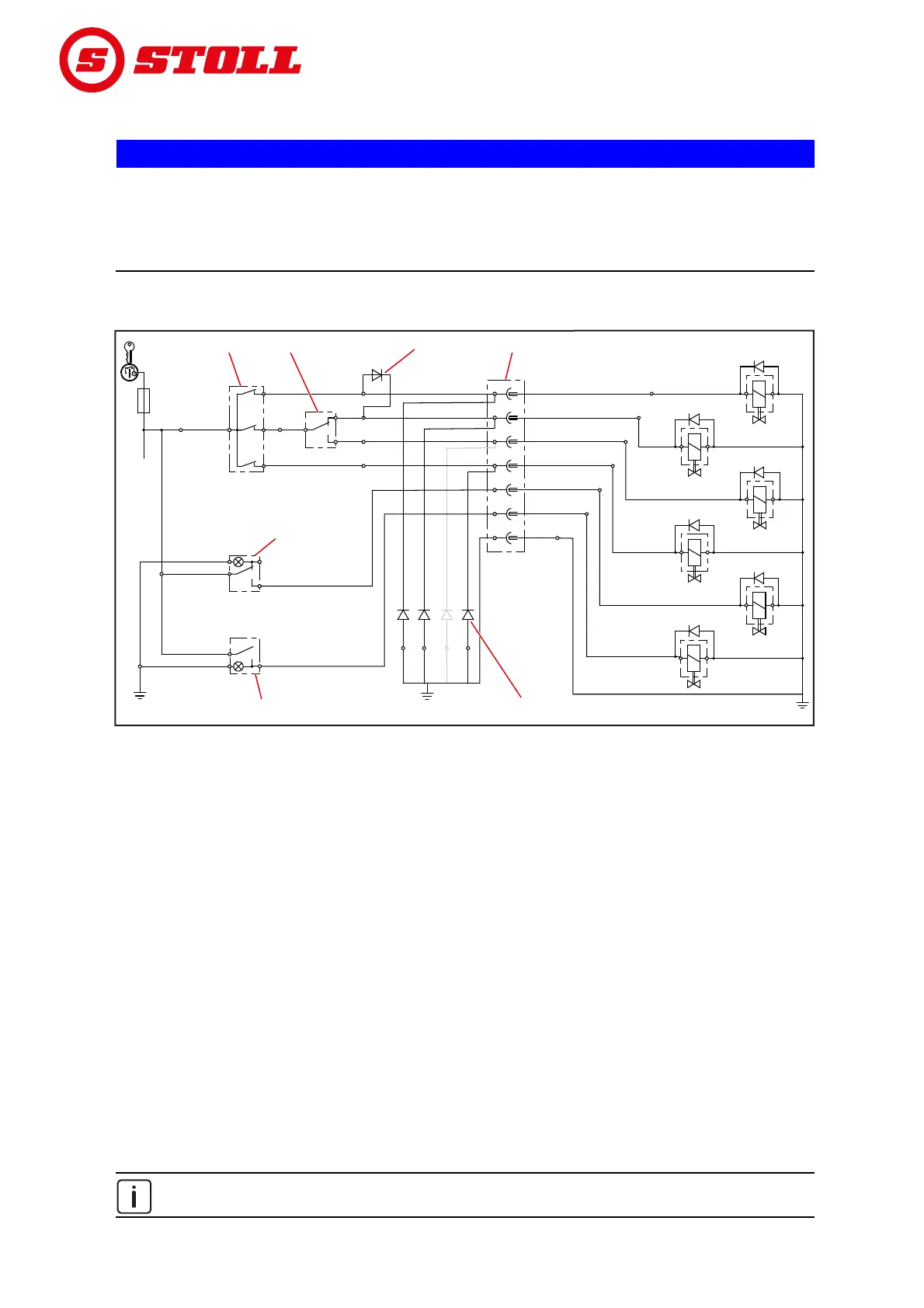
11.5 Electric circuit diagram
NOTICE
Material damage due to improper tensioning or lacking fuse!
If the rated voltage of 12 V is exceeded or the ignition lock is not switched, the system can be damaged.
Switch the rated voltage of 12 V via the ignition lock.
The connection must be protected with a fuse.
The optional functions Q1 to Q6 on the front loader lifting arm are shown in simplified form, as they may
vary depending on the type of front loader.
Fig. 104 Electric circuit diagram
This circuit diagram does not apply to tractors with a Pro Control single-lever control unit!
In this case, please observe the Pro Control assembly and operating instructions.
Legend
Q1 4th control circuit
Q2 3rd control circuit
Q3 Rapid emptying (FS-rapid emptying) or quick emptying (FZ L)
Q4 Return-To-Level (FZ-L)
Q5 Comfort Drive
Q6 Hydro-Lock (hydraulic implement locking mechanism)
A Button on the operating lever (on some operating levers with relay)
-S2: 3rd control circuit, quick emptying or rapid emptying
-S4: additional scooping or Return To Level
-S1: 4th control circuit
B -S3: Changeover switch 3rd control circuit / rapid emptying or quick emptying
C Comfort-Drive switch, with pilot lamp
D Hydro-Lock rocker switch, with pilot lamp
E Suppressor diode 4th control circuit, button S1 simultaneously activates valve Q2 for the 3rd control circuit and
switches this function via shuttle valve Q1 to the 4th control circuit.
F Suppressor diodes: reduce disruptions caused by the solenoid valves.
Depending on the equipment, the suppressor diodes on FS front loaders are used on terminals 1, 2 and/or 3, and
with FZ front loaders, they are on terminals 1, 2 and/or 4.
G Plug / socket
44
33
1
2
1
2
77
5
6
5
6
2
3
1
2
7
3
1
7
2
-S1
-S5
-F1
-S6
-Q6
-Q5
-Q4
-Q3
-Q2
-Q1
-R4
-R3
(FS)
-R2
-R1
-S4
-S2
-S3
bk
rd
ye
wh
bu
bn
gn/ye
bu
bu
bn
bk
bk
bk
bk
bk
bn
-R3
(FZ)
+12 V+12 V
Q1
Q1
10 A
10 A
A
A
Q6Q6
Q5
Q5
Q4
Q4
Q3
Q3
Q2
Q2
E
E
D
D
C
C
B
B
F
F
GG
B082