B58FZS 0000000078 EN 002 48
FUNCTIONS
Setting the return-to-level position:
(1) Position the implement horizontally.
(2) Lower the front loader to the ground.
(3) Switch off the tractor.
Apply the parking brake.
Stop the engine.
(4) Loosen the clamping screw.
(5) Push the tube in the support until there is a
space of about 10 mm between the top end
of the rod and the top edge of the sensor.
(6) Tighten the clamping screw.
(7) Switch on the tractor.
(8) Lift and dump the front loader.
(9) Slowly lower the front loader and press the
RTL button at the same time
(see 6.1 Operating elements).
(10) Check the position of the implement.
If necessary, push the tube up or down.
The return-to-level position is set.
4.8 Anti-lowering guard
⚠ WARNING
Risk of injury and accident due to implement tipping off!
The anti-lowering guard only prevents the front loader from lowering, however, it does not prevent
accidental dumping of the implement. Persons whose presence is required near the load can be injured
by the load falling down.
Do not move the front loader as long as people are standing in the danger zone.
Only start the lifting operation after everybody has left the danger zone.
The anti-lowering guard in compliance with EN 12525/A1 prevents sudden lowering of the front loader.
It is used when working with a raised front loader if the presence of persons is required in the machine's
working area.
The anti-lowering guard is not suitable for use with work cages that are used to transport people.
The operating state of the anti-lowering guard is shown by the lamp on the switch box. If the lamp is on,
the anti-lowering guard is activated. If the lamp is off, the anti-lowering guard is deactivated. In this case,
there may not be any one standing in the working area of the front loader (see 2.8 Danger zones). When
the anti-lowering guard is activated, the lifting function is possible and the lowering function is locked.
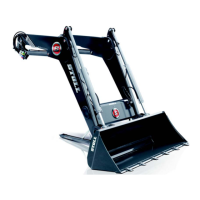
Fig. 32 Return-to-level sensor on the indicator
Legend
1 Sensor
2 Clamping screw
3Holder
4 Tube
5Rod